
Orbiting power plant

a power plant and orbiting technology, applied in the direction of electric generator control, machines/engines, mechanical equipment, etc., can solve the problems of global climate change, imbalance in earth's atmospheric composition, and threat to civilization, and the dependence on foreign oil poses a threat to the economy

Inactive Publication Date: 2010-10-21
FLOOD KERRY A
View PDF24 Cites 13 Cited by
  • Summary
  • Abstract
  • Description
  • Claims
  • Application Information

AI Technical Summary

Benefits of technology

[0021]In more detailed aspects, there is provided an orbiting power plant for generating electrical energy in a microgravity environment from solar radiation, the orbiting power plant comprising a hull, an electrical generator disposed in the hull and having an input and an output, the generator comprising a moving electrical device at the input, the generator configured to produce electrical energy at the output in response to the application of energy to the moving electrical device at its input, wherein the moving electrical device has a first movement direction, a radiation collection system configured to receive solar radiation energy and direct the solar radiation energy to a predetermined position on the hull, a working-fluid engine comprising a first stage disposed at the predetermined position on the hull at which a lower-energy-state working fluid absorbs the directed solar radiation energy to result in a higher energy state of the working fluid, a second stage at which the higher energy state working fluid is applied to the moving electrical device at the input of the generator at which at least some of the energy of the working fluid is transferred to the moving electrical device whereby electrical energy is generated, and a third stage at which the higher-energy-state working fluid releases energy to result in a lower energy state, and a pseudo gravity generation system to which the higher-energy-state working fluid is applied to transfer energy to said pseudo gravity system, the pseudo gravity generation system configured to generate a pseudo gravity environment in the orbiting power plant in response to the energy from the working fluid thereby producing a buoyant force in the hull to enable operation of the working-fluid engine and providing force that opposes tendency of the hull to move with the moving electrical device of the generator.
[0022]In more detailed aspects, the moving electrical device comprises a rotor with attached generator turbine to which energy of the working fluid is applied to cause rotation of the rotor in the first movement direction to generate electrical energy. The pseudo gravity system comprises a hull turbine to which the working fluid is applied to impart rotational force to the hull opposite to the rotation direction of the rotor to oppose tendency of the hull to move with the rotor. The generator turbine and the hull turbine are co-located with the generator turbine disposed within the hull turbine, with both turbines having a plurality of turbine blades with

Problems solved by technology

Dependence on foreign oil poses a threat to the economy of any country of the world, creating a need for the development of alternatives.
Additionally, the use of fossil fuels is a proven cause of imbalance in the earth's atmospheric composition.
The large-scale use of fossil fuels has produced conditions whereby global climate change poses an increasingly grave threat to civilization.
If radical climate change is not prevented, it could trigger an ecological collapse that would undermine the capacity of the earth to support known life forms.
Such methods have proven to be either impractical or have not been suitably developed for widespread use.
At this time, no viable solutions have been implemented and the rate of the earth's natural processes which normally balance the concentration of such gases has been exceeded by man-made emissions.
The construction of massive hydroelectric sources such as the Hoover Dam is an example of a power source that is not cost effective.
Even our most reliable sources are now threatened by the increasing frequency and intensity of storms caused by the changing climate.
Although accessible coal deposits could last for centuries, it remains a non-renewable fossil fuel and cannot be relied upon indefinitely.
Another limiting factor to the viability of coal power plants is the need for water to cool steam used to drive generators.
In some areas, water availability has become a problem as population increases.
As climate change progresses, this problem is expected to worsen.
As limits are reached on the amount of water available, conflicts in use arise.
Since the changes in climate include drying of the southwestern U.S. and less water in the Colorado River Basin, it is readily seen that such conflicts of water use can only lead to increasing hardship.
The conflicts between the supply and demand for food, water, and electricity to maintain our lifestyles have led to destructive exploitation of natural resources in foreign countries.
Nuclear power plants can provide reliable power; however, cost is a nearly incalculable factor, since the risk and potential consequences vastly outweigh the value of any possible economic return.
Aside from potentially significant environmental hazards, widespread use of nuclear fuel for power generation would necessarily proliferate nuclear technology, which is an unwise course considering current political conditions.
Nuclear power technology has been generally rejected by the public as unviable from a risk/benefit standpoint.
Development of sufficient nuclear power generation capacity to replace existing coal plants would be logistically problematic since large quantities of water are required to keep nuclear cores cool.
The Seabrook plant constructed off the coast of New Hampshire was closed within a few years of operation due to the negative effect caused by the use of ocean water for cooling.
Nuclear power is an undesirable alternative to fossil fuels.
Although existing wind power technology provides energy without the

Method used


Image

  • Orbiting power plant
  • Orbiting power plant
  • Orbiting power plant

Examples


Embodiment Construction

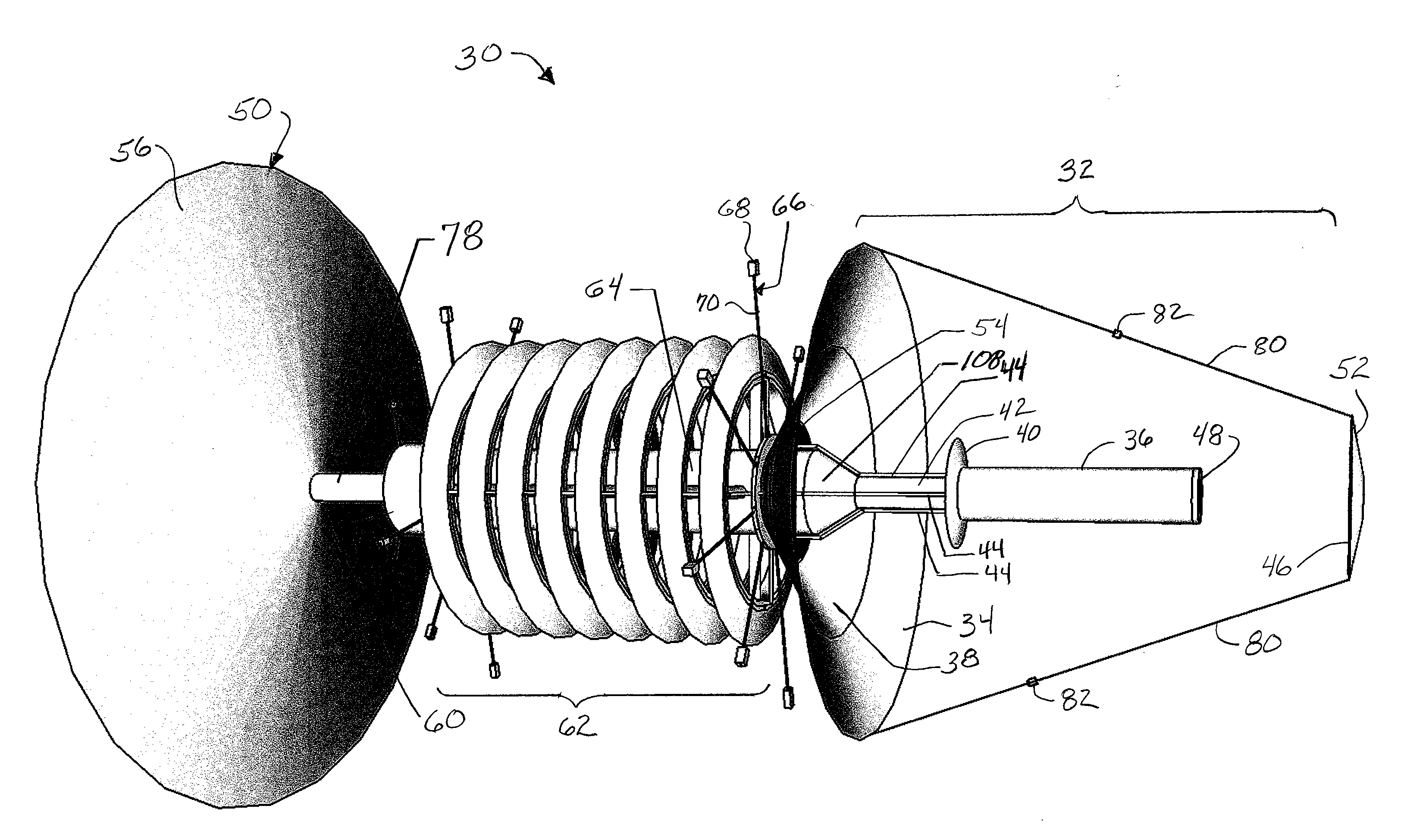
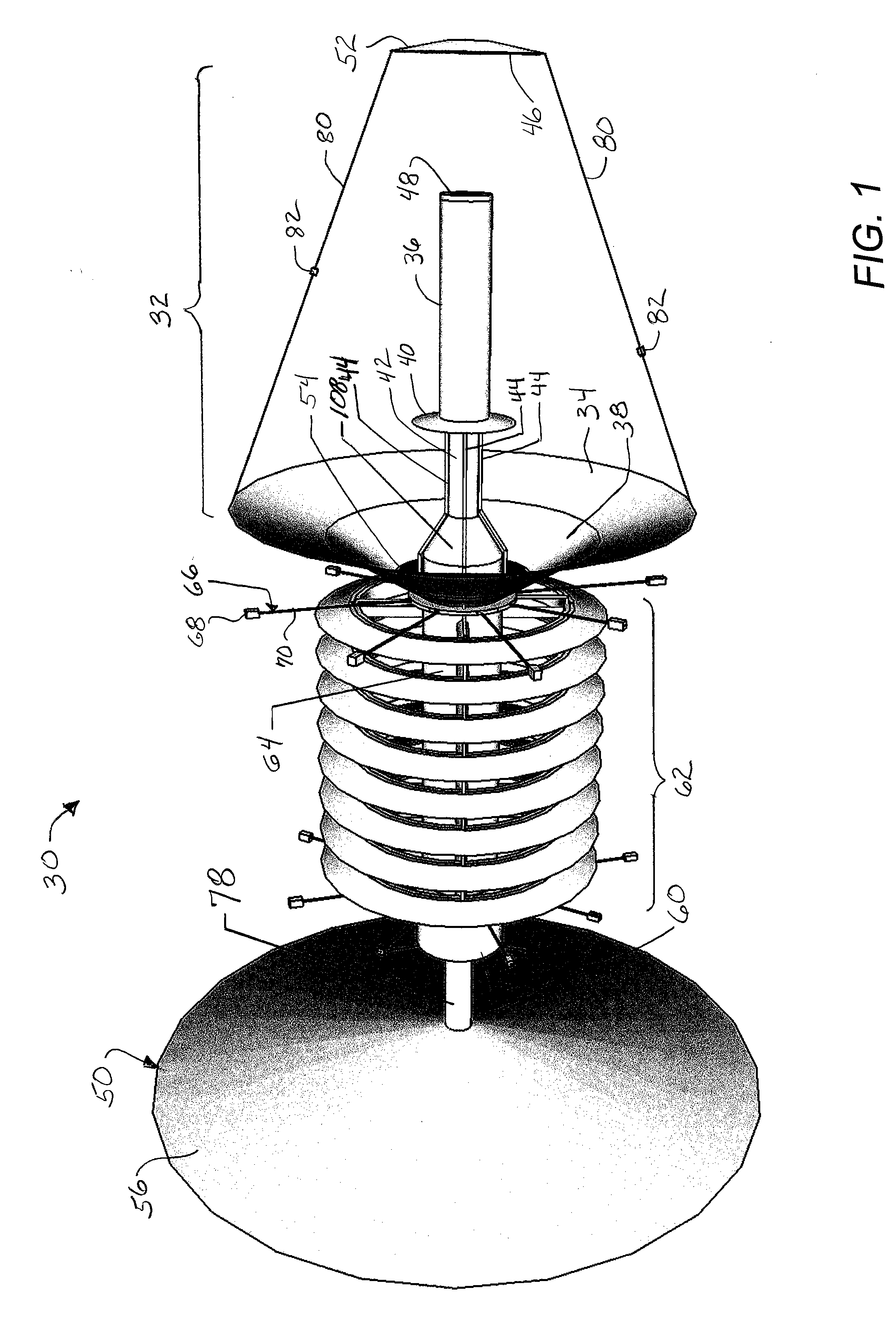
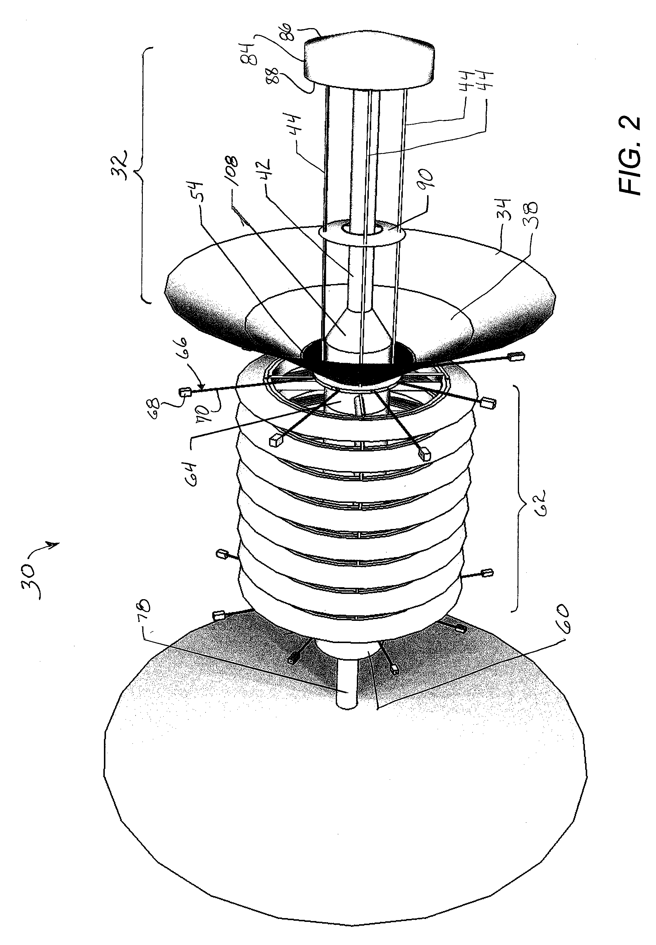
[0049]Referring now in more detail to the exemplary drawings for purposes of illustrating embodiments of the invention, wherein like reference numerals designate corresponding or like elements among the several views, there is shown in FIG. 1 a frontal perspective view of an orbiting power plant 30 for generating electrical energy in a micro-gravity environment according to aspects of the invention. Although not shown, a solar radiation source would be located to the right side of the figure for providing solar radiation to the power plant. One obvious solar radiation source is the sun and in that particular application, the orbiting power plant 30 would be orbiting the earth. The terms “power plant,”“power generating system,”“power generating satellite,”“space craft,” and “space vehicle,” are used interchangeably herein and are meant to be descriptive of an embodiment or embodiments, and not meant to be limiting.

[0050]For convenience, in the following detailed descriptions of embod...


PUM


Abstract

A self-contained orbiting power plant receives and directs solar radiation as an energy source to heat the working fluid of a Rankine-type engine used to power an electrical energy generator and create a pseudo-gravity environment in which the buoyant force exists. Through the use of reflectors and alignment of the power plant with the solar radiation source, the low temperature of outer space is used as a heat sink to condense steam back into the liquid phase. The working fluid (e.g. water) is pressurized and heated to the elevated vaporization point and the expansion of the superheated steam is captured through rotation of the power plant in the microgravity environment. The steam is used to rotate an electrical generator turbine and a counter-rotation hull turbine. The steam is cooled by conductive heat transfer to a cooling fluid (e.g. liquid ammonia) which radiates excess heat to outer space, and to return the working fluid to the liquid phase for recirculation. The produced electrical current is transformed and transmitted as microwave energy. The power generated may be transformed to specific transmittable wavelengths to decompose greenhouse gases in the atmosphere during transmission.

Description

BACKGROUND OF THE INVENTION[0001]The invention is generally related to power generation and, more particularly, to a power plant orbiting above the earth adapted for generating electrical power from solar energy.[0002]Dependence on foreign oil poses a threat to the economy of any country of the world, creating a need for the development of alternatives. Additionally, the use of fossil fuels is a proven cause of imbalance in the earth's atmospheric composition. The large-scale use of fossil fuels has produced conditions whereby global climate change poses an increasingly grave threat to civilization. If radical climate change is not prevented, it could trigger an ecological collapse that would undermine the capacity of the earth to support known life forms. In order to avoid the worst consequences of global climate change, the 2007 Intergovernmental Panel on Climate Change (IPCC) report suggested a ten-year window of opportunity to reduce global greenhouse gas emissions to pre-1990 l...

Claims


Application Information

Patent Timeline
IPC IPC(8): H02K7/18F03G6/06
CPCB64G1/44Y02E10/46H02K7/1823F01K7/16
Inventor FLOOD, KERRY A.
Owner FLOOD KERRY A
Learn More