Driving method of field sequential display

Active Publication Date: 2010-10-21
NUVOTON +1
View PDF4 Cites 16 Cited by
  • Summary
  • Abstract
  • Description
  • Claims
  • Application Information

AI Technical Summary

Benefits of technology

[0011]The present invention provides a method of driving a field sequential display apparatus, in whic

Problems solved by technology

This arrangement not only results in high production costs, but also gives rise to color deviation problems at the adjacent boundaries of each of the red, green, and blue color filters.
In addition, since liquid crystal displays are manufactured with color filter structure, the white light sources experience brightness degra

Method used


Image

  • Driving method of field sequential display
  • Driving method of field sequential display
  • Driving method of field sequential display

Examples


Embodiment Construction

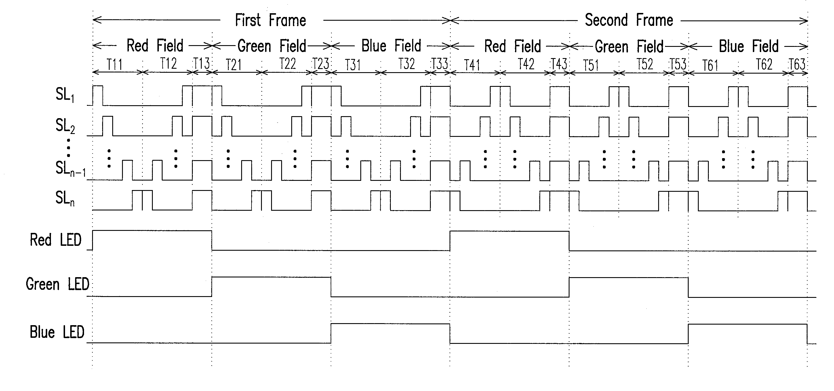
[0030]FIG. 2 is a schematic view illustrating the driving waveform of a field sequential display apparatus according to one embodiment of the present invention. As shown in FIG. 2, there is a first frame, and within the first frame there is a red field, a green field, and a blue field. The red field (or the first field) will be described first. In the red field, red LEDs are lit to provide red backlights. During period T11 (or the first period), the scan lines SL1 to SLn are sequentially driven by the field sequential display apparatus according to the scanning sequence. Assuming here that the scanning sequence is from the scan line SL1 to the scan line SLn, then the field sequential display apparatus sequentially drives scan lines SL1 to SLn in order to write in the corresponding pixel data. This allows the field sequential display apparatus to display images in the red field. Herein, the time of driving the scan lines SL1 to SLn can be uniform, meaning that the time of driving the...


PUM


Abstract

A driving method of a field sequential display apparatus is provided. First, a plurality of scan lines of the field sequential display apparatus are sequentially driven according to a scanning sequence in a first period of a first field, wherein the first field is in a first frame. Next, the scan lines are sequentially driven according to an opposite sequence in a second period of the first field, wherein the opposite sequence is in the reverse order of the scanning sequence. Finally, the scan lines are simultaneously driven or not driven in a third period of the first field. Consequently, the disclosed driving method can promote the uniformity of the image brightness.

Description

CROSS-REFERENCE TO RELATED APPLICATION[0001]This application claims the priority benefit of Taiwan application serial no. 98113010, filed Apr. 20, 2009. The entirety of the above-mentioned patent application is hereby incorporated by reference herein and made a part of specification.BACKGROUND OF THE INVENTION[0002]1. Field of the Invention[0003]The present invention generally relates to a technology of a flat panel display; more specifically, to a method of driving a field sequential display apparatus.[0004]2. Description of Related Art[0005]In conventional liquid crystal displays, the light source designs of backlight modules usually do not venture far from white light sources (usually white light emanating from cold cathode tubes). The white light usually passes through color filters to form the backlight source needed for each of the pixels. From the perspective of an array of pixels, there is a red color filter, a green color filter, and a blue color filter above each pixel. Th...

Claims


Application Information

Patent Timeline
IPC IPC(8): G09G5/00
CPCG09G3/3648G09G2310/0235G09G2320/0233G09G2310/067G09G2310/0283
Inventor CHANG, PAO-SHU
Owner NUVOTON
Why Eureka
Try Eureka