Light output device

a technology of light output and semiconductor, which is applied in the direction of semiconductor devices for light sources, lighting and heating apparatus, instruments, etc., can solve the problems of not giving uniform illumination, affecting the transparency of the structure in the non-, and the semiconductor leds are point sources. achieve the effect of increasing the level of light uniformity

Active Publication Date: 2010-10-21
SIGNIFY HLDG BV
View PDF11 Cites 18 Cited by
  • Summary
  • Abstract
  • Description
  • Claims
  • Application Information

AI Technical Summary

Benefits of technology

[0023]The scattering carried out by the switchable layer increases the level of uniformity of the light. Thus, a higher level of uniformity of the light is to be understood to mean a more uniform light output over a given area.

Problems solved by technology

One problem with this type of device is that semiconductor LEDs are point sources.
As a result, the LEDs appear as bright dots of light, which is not always preferred, and does not give uniform illumination.
However, this affects the transparency of the structure in the non-illuminating state, which is undesirable.

Method used


Image

  • Light output device
  • Light output device
  • Light output device

Examples


Embodiment Construction

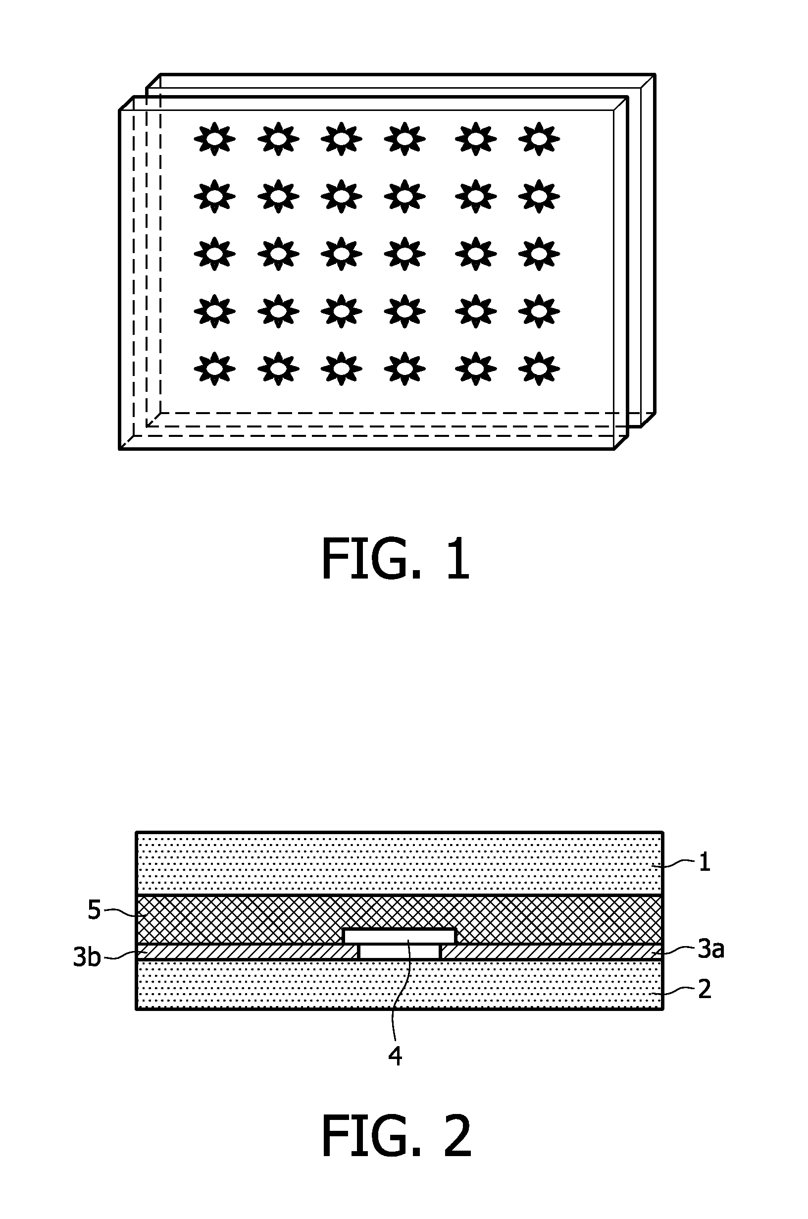
[0038]FIG. 2 shows a known LED in glass structure. The light output device comprises glass plates 1 and 2. Between the glass plates are (semi-) transparent electrodes 3a and 3b (for example formed using ITO or thin conductive wires), and a LED 4 connected to the transparent electrodes 3a and 3b. A layer of thermoplastic material 5 is provided between glass plates 1 and 2 (for example PVB or UV resin).

[0039]When transparent electrodes are used, they are not visible to the viewer, and they do not introduce non-uniformities to the light output.

[0040]The electrodes are preferably substantially transparent, by which is meant that they are imperceptible to a viewer in normal use of the device. If the conductor arrangement does not introduce a noticeable variation in light transmission (for example because it is not patterned, or because the pattern cannot be seen), a transparency of greater than or equal to 50% may be sufficient for the system to appear transparent. More preferably, the t...


PUM


Abstract

A light output device comprises at least one light source having a light source output comprising at least a light output, and a switchable member through which the light output is provided, and which is switchable between at least two optical states. These at least two opticalstates provide different levels of uniformity of the light output. The switching of the switchable member is induced by the light source output.

Description

FIELD OF THE INVENTION[0001]This invention relates to light output devices, particularly but not exclusively using discrete light sources associated with a transparent substrate structure.BACKGROUND OF THE INVENTION[0002]One known example of this type of lighting device is a so-called “LED in glass” device. An example is shown in FIG. 1. Typically a glass plate is used, with a transparent conductive coating (for example ITO) forming electrodes. The conductive coating is patterned in order to make the electrodes that are connected to a semiconductor LED device. The assembly is completed by laminating the glass, with the LEDs inside a thermoplastic layer (for example polyvinyl butyral, PVB).[0003]Applications of this type of device are shelves, showcases, facades, office partitions, wall cladding, and decorative lighting. The lighting device can be used for illumination of other objects, for display of an image, or simply for decorative purposes.[0004]One problem with this type of dev...

Claims


Application Information

Patent Timeline
Patent Type & Authority Applications(United States)
IPC IPC(8): F21V1/00
CPCF21V14/003F21Y2101/02F21Y2105/001G02F1/0126G02F1/0147Y02B20/125H01J61/025H01K1/26H01K1/28H01K1/34G02F2203/03F21Y2105/10F21Y2115/10Y02B20/00
Inventor VAN HERPEN, MAARTEN MARINUS JOHANNES WILHELMUSPENTERMAN, ROEL
Owner SIGNIFY HLDG BV
Why Eureka
Try Eureka