Toner-density calculating method, reflective optical sensor, and image forming apparatus

a toner density and calculating method technology, applied in the direction of electrographic process, electrographic process apparatus, instruments, etc., can solve the problems of difficult to always keep, difficult to calculate toner density, and difficult to see toner image formation

Inactive Publication Date: 2010-10-21
RICOH KK
View PDF29 Cites 46 Cited by
  • Summary
  • Abstract
  • Description
  • Claims
  • Application Information

AI Technical Summary

Benefits of technology

[0032]It is an object of the present invention to at least

Problems solved by technology

If the toner density is high, i.e., if the amount of the toner supplied to the electrostatic latent image is more than the necessary amount, a darker and difficult-to-see toner image will be formed.
However, it is difficult to always keep a relative position between the toner pattern and the reflective optical sensor in the main-direction the ideal state, due to various reasons.
If a portion of the spot falls in a region where there is no toner pattern because of the positional miss-match in the main-direction between the toner pattern and the reflective optical sensor, the reflected light received by the light-receiving unit represents wrong data, and therefore the calculated toner density is wrong.
Because the toner-density calculation is performed as the maintenance activity separated from the main activity, i.e., an image-forming process, the image forming operation cannot be perf

Method used


Image

  • Toner-density calculating method, reflective optical sensor, and image forming apparatus
  • Toner-density calculating method, reflective optical sensor, and image forming apparatus
  • Toner-density calculating method, reflective optical sensor, and image forming apparatus

Examples


Embodiment Construction

[0133]Exemplary embodiments of the present invention are described in detail below.

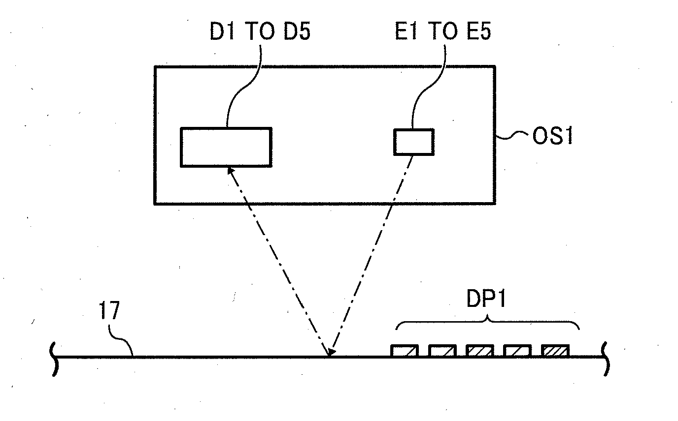
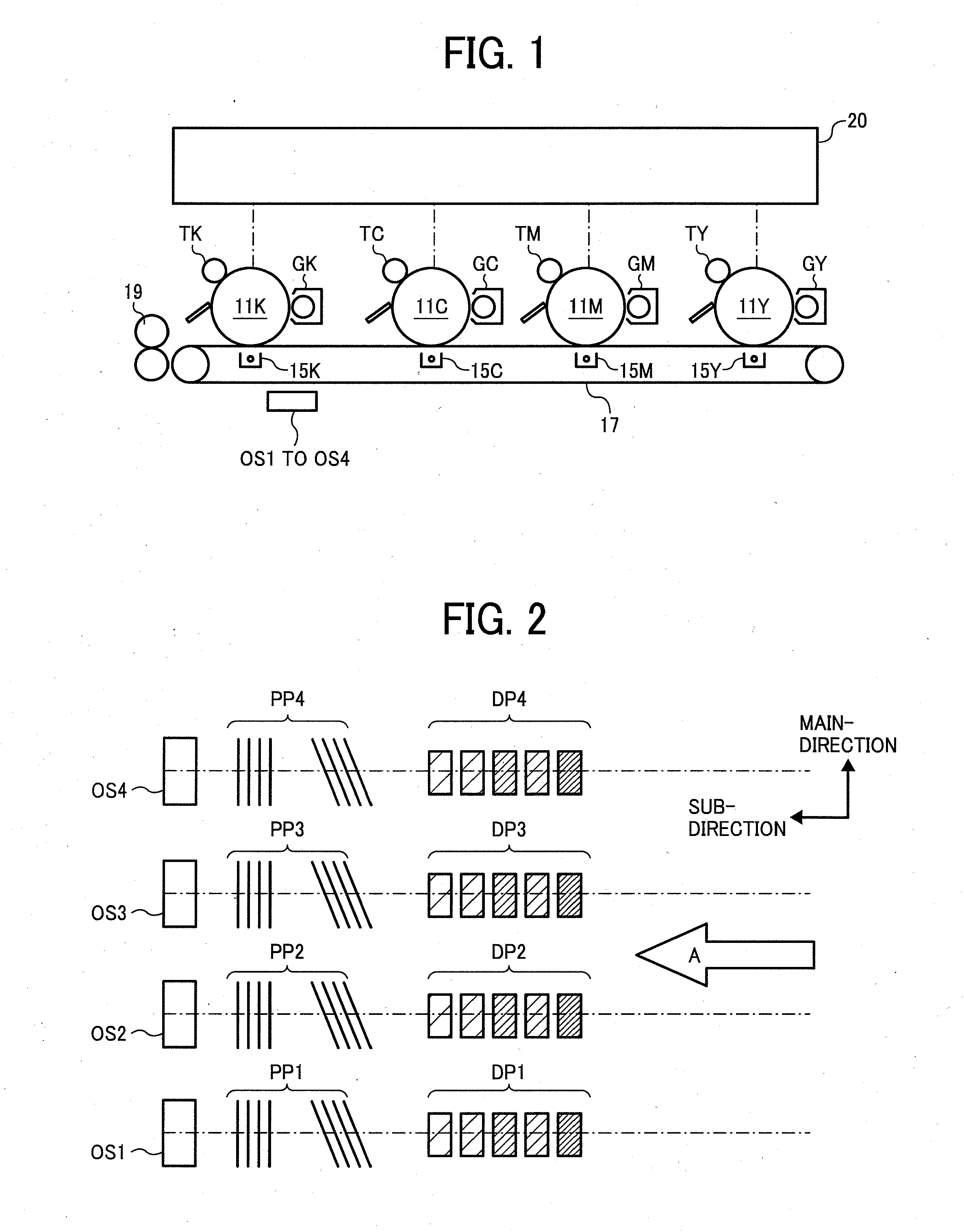
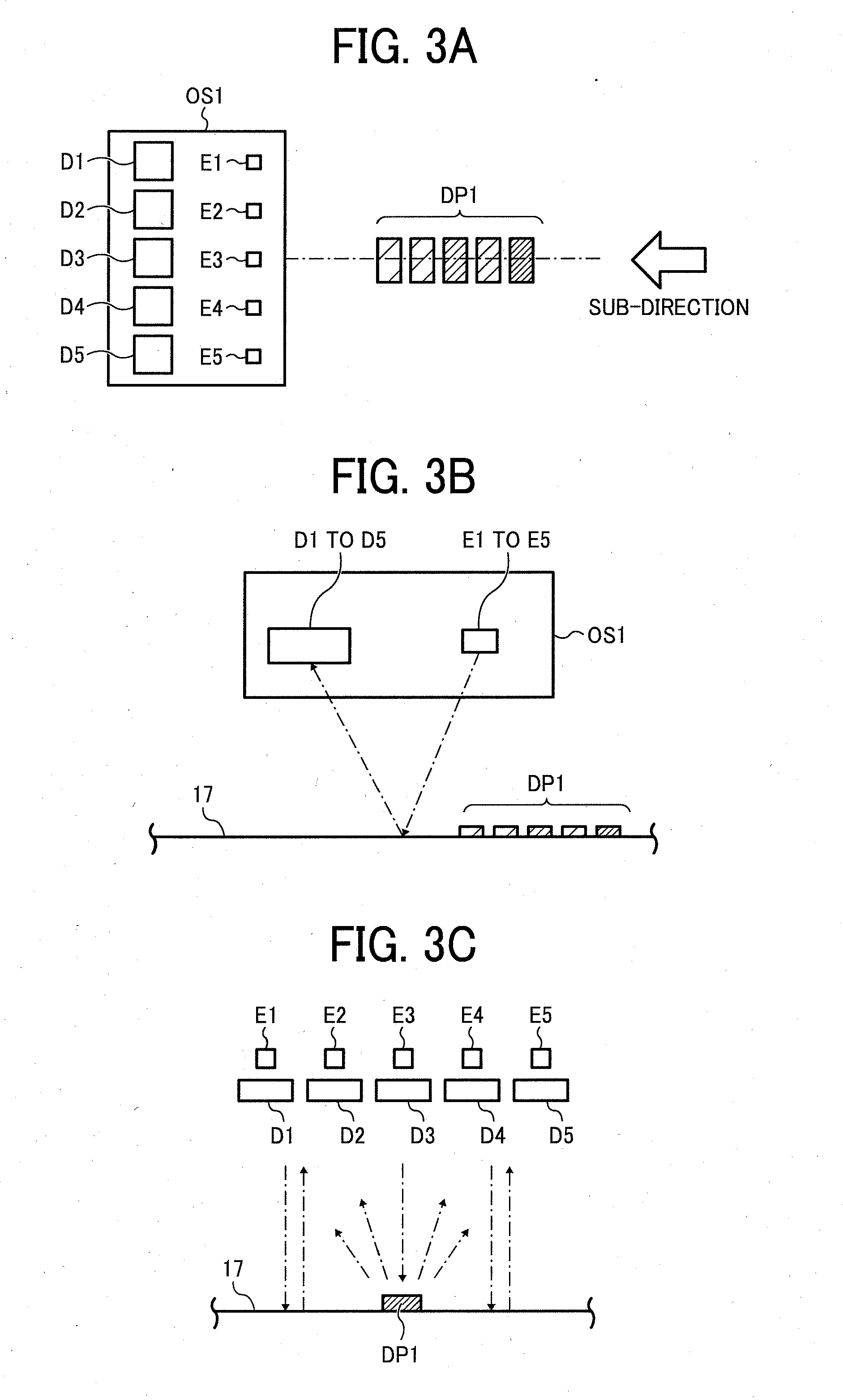
[0134]A density calculating method according to the present embodiment involves, in a method of forming images with toner, forming a predetermined toner pattern on a supporting member moving in a predetermined sub-direction, causing a light-emitting unit to illuminate the supporting member with detection light, receiving the light reflected by the supporting member and / or the toner pattern at a light-receiving unit, and calculating the toner density using difference between characteristics of the supporting member reflecting the detection light and characteristics of the toner pattern reflecting the detection light.

[0135]The method of forming images with toner is used in the copiers, the printers, the plotters, the facsimile machines, the MFPs, etc. The method of forming images with toner includes the process of forming the electrostatic latent image and the process of developing the electrostatic lat...


PUM


Abstract

In a reflective optical sensor in an image forming apparatus, an output from each N number of light-receiving elements (N≧3), obtained when M number of light-emitting elements (M≧3) included in a light-emitting unit emit detecting light, is separated into an amount of specularly reflected light and an amount of diffusely reflected light. The toner density of a pattern, which is formed on a supporting member in the image forming apparatus, is calculated based on a sum of the amounts of specularly reflected light and a sum of the amounts of diffusely reflected light.

Description

CROSS-REFERENCE TO RELATED APPLICATIONS[0001]The present application claims priority to and incorporates by reference the entire contents of Japanese Patent Application No. 2009-101691 filed in Japan on Apr. 20, 2009 and Japanese Patent Application No. 2009-213665 filed in Japan on Sep. 15, 2009. The present application incorporates by reference the entire contents of Japanese Patent Application No. 2008-238487 filed in Japan on Sep. 17, 2008.BACKGROUND OF THE INVENTION[0002]1. Field of the Invention[0003]The present invention relates to a toner-density calculating method, a reflective optical sensor that is used in the toner-density calculating method, and an image forming apparatus. The image forming apparatus is provided, for example, in a multifunction product (MFP) that includes the reflective optical sensor and works as at least one of a copier, a printer, a facsimile machine, and a plotter.[0004]2. Description of the Related Art[0005]A variety of image forming apparatuses use...

Claims


Application Information

Patent Timeline
IPC IPC(8): G03G15/00G01N21/55G03G15/01G03G15/08
CPCG01N21/55G01N2021/556G03G15/0131G03G15/0178G03G15/0855G03G2215/0132G03G2215/0164G03G15/0827G03G15/5058G03G15/50
Inventor SUZUKI, HIDEMASAMASUDA, KOJI
Owner RICOH KK
Why Eureka
Try Eureka