Battery pack

a battery pack and battery technology, applied in the field of batteries, can solve the problems of low workability in connecting individual battery cells, affecting the efficiency of battery cell connection, and reducing the volumetric efficiency of long wires, so as to improve the efficiency of connecting a large number of cells

Inactive Publication Date: 2010-10-21
KK TOSHIBA
View PDF2 Cites 39 Cited by
  • Summary
  • Abstract
  • Description
  • Claims
  • Application Information

AI Technical Summary

Benefits of technology

[0007]The present invention was contrived in order to solve the problems of the conventional technology described above, and an object of the present invention is to provide a battery pack, in which a plurality of cells connected by bus bars are unitized, thus obtained unit is combined and connected with another unit or cells to configure a battery module, so that external connection terminals are arrayed in the same direction in the module having the plurality of cells connected in series and a wiring that cuts across the module is not generated, furthermore, in which improvement of the workability and reduction of connection failures are achieved by only connecting between the units by means of a bus bar when creating the module.
[0010]As a result of using the present invention, because the wiring connection terminals of the battery module can be arranged in proximity to each other in the same direction, a wiring cutting across the module is no longer necessary. Moreover, a module with more cells is created by using a three-piece unit or two-piece unit having a plurality of cells, whereby the efficiency of connecting a large number of cells is improved.

Problems solved by technology

Thus, use of a long wiring significantly reduces the volumetric efficiency more, compared to the structure in substantially a cubic shape.
Although it is preferred to use a highly rigid bus bar or other conductive member to reduce the connection resistance between the cells, it is troublesome to prevent each of the plurality of bus bars from intersecting with another bus bar, or to connect the bus bars to discretely and individually provided cells, and there is a problem where connection failures occur.
As described above, the problems of the conventional technology are that the workability in connecting individual battery cells is low and therefore connection failures occur easily because the individual battery cells are connected one by one by a bus bar, and that the length of a wiring increases because the electric power is extracted from the terminals on both ends of each of serially connected modules to the outside.

Method used


Image

  • Battery pack
  • Battery pack
  • Battery pack

Examples


first embodiment

1. First Embodiment

[0031]A first embodiment of the present invention is described hereinafter in detail with reference to FIGS. 1 to 3.

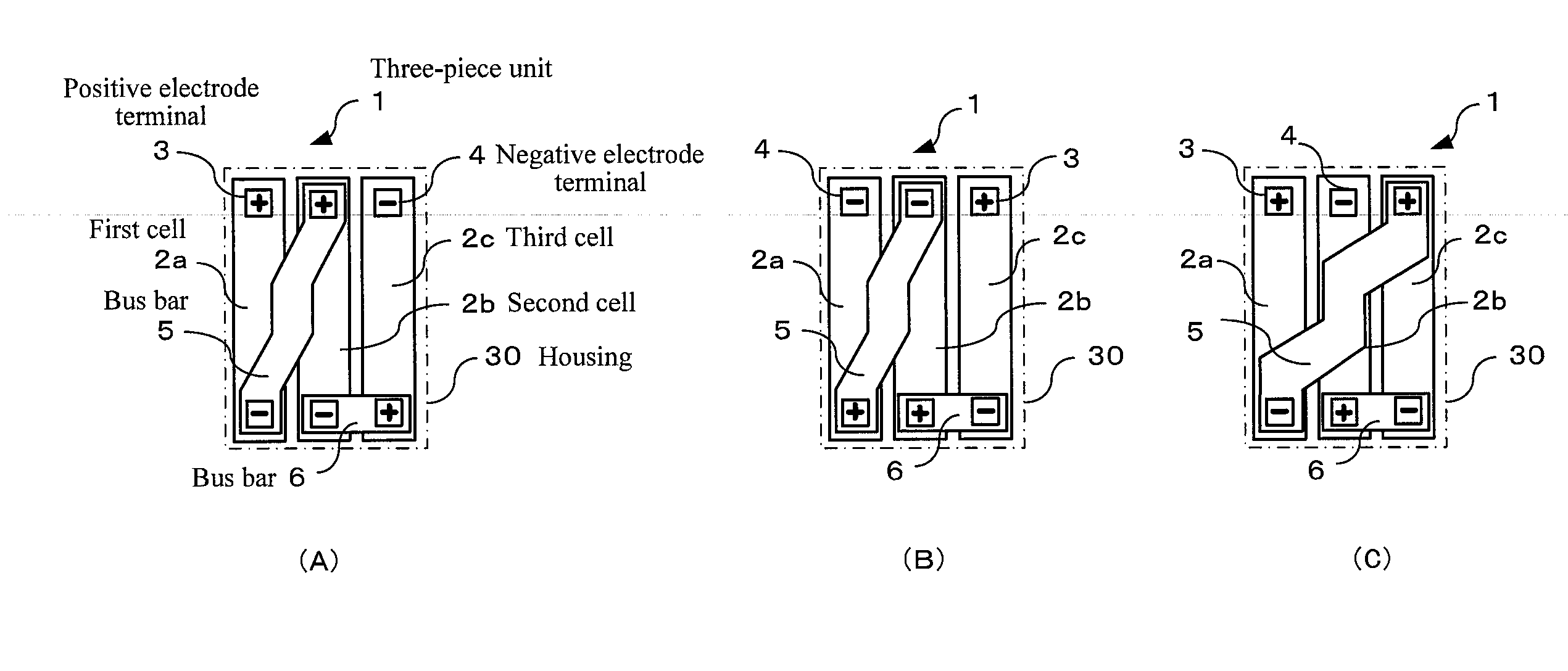
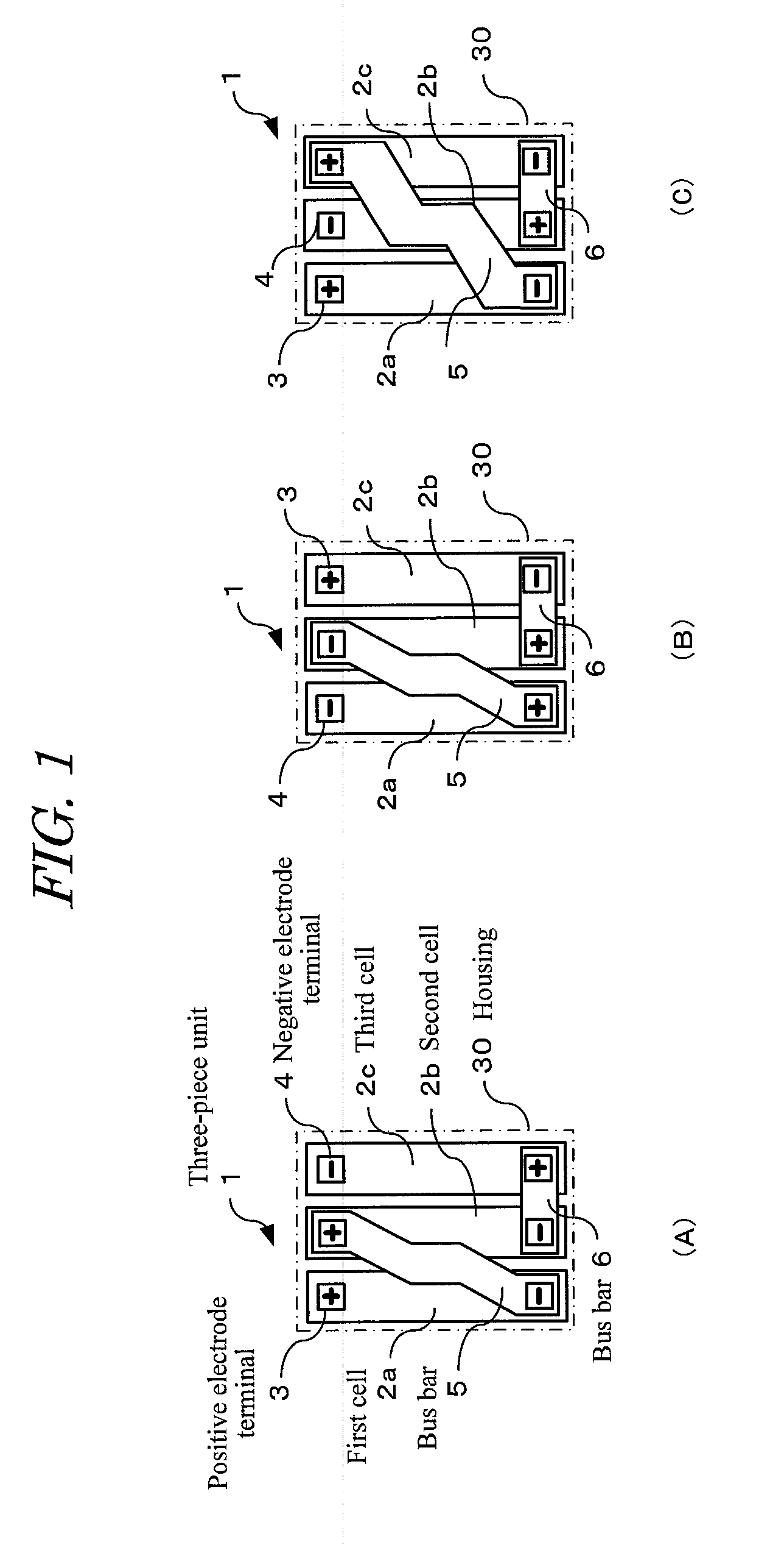
[0032]FIG. 1(A) shows a three-piece unit 1 of a battery pack of the present embodiment. In this three-piece unit 1, three pieces of flat-plate cells 2a to 2c are arranged in parallel along the longitudinal direction thereof, and a positive electrode terminal 3 and negative electrode terminal 4 are provided at the top of each of the cells 2a to 2c. In this case, in the first and second cells 2a, 2b the positive electrode terminals 3 and the negative electrode terminals 4 are arranged in the same direction, and in the third cell the positive electrode terminal 3 and the negative electrode terminal 4 are arranged in direction opposite to each other.

[0033]The negative electrode terminal 4 of the first cell 2a and the positive electrode terminal 3 of the second cell 2b are connected with each other by an internal connection bus bar 5 disposed in an obliqu...

second embodiment

2. Second Embodiment

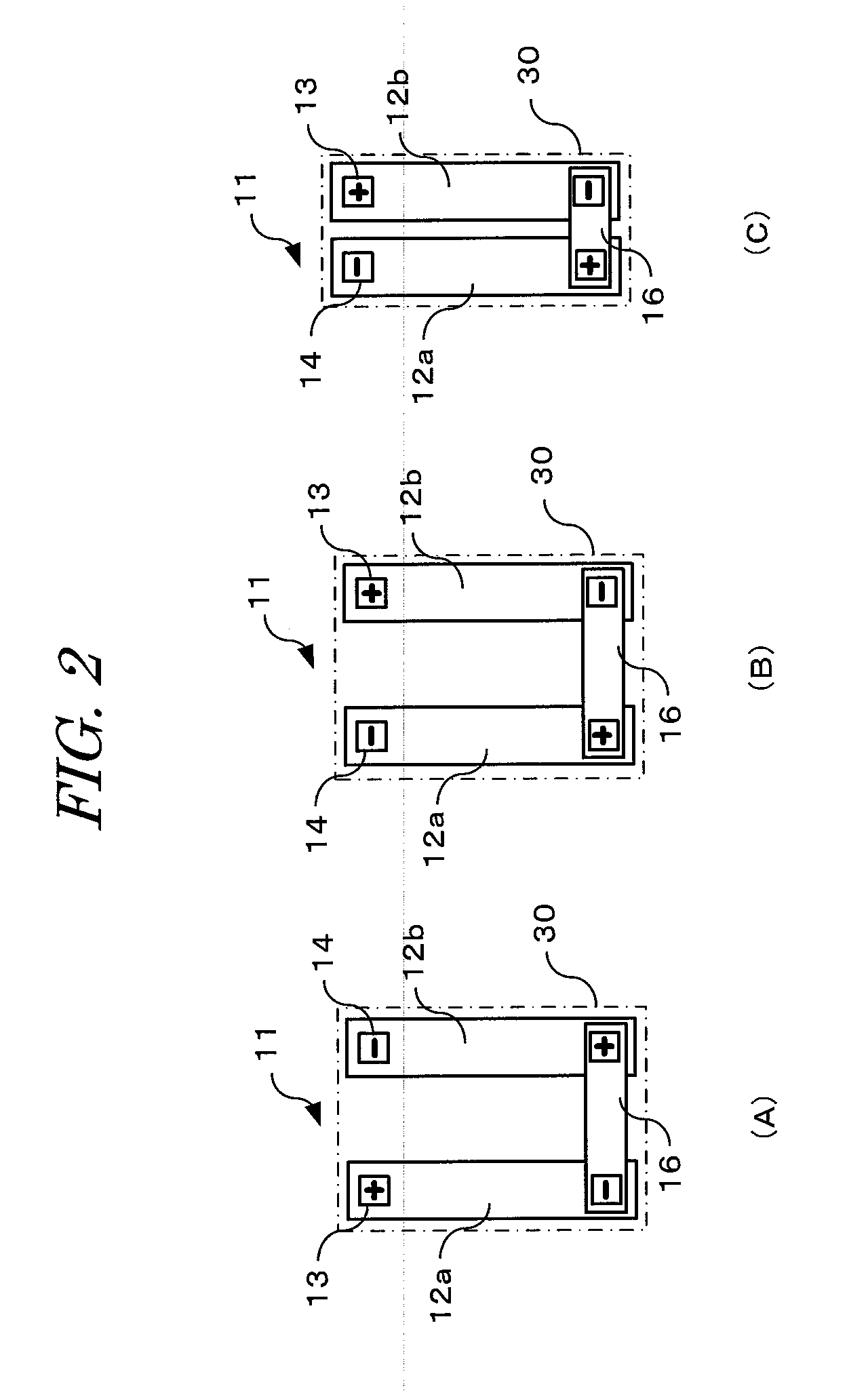
[0040]In FIG. 4, in addition to the three-piece unit 1 and the two-piece unit 11 shown in FIGS. 1 and 2, a different type of three-piece unit 1′ and different type of two-piece unit 11′ that are similarly configured by storing three or two cells in the housing 30 are used for connecting ten cells in series.

[0041]In this embodiment, as with the three-piece unit shown in FIG. 1, the three-piece unit 1′ has the oblique bus bar 32 for connecting the positive electrode terminal with the negative electrode terminal in each of adjacent cells. However, this bus bar 32 is not an internal connection bus bar for connecting the cells of the unit beforehand, but an external connection bus bar that connects the positive electrode terminal and the negative electrode terminal of the cell exposed from the housing 30, from the outside of the housing 30. In this three-piece unit 1′, the positive electrode terminal and the negative electrode terminal of each of the three cells are e...


PUM

PropertyMeasurementUnit
lengthaaaaaaaaaa
voltageaaaaaaaaaa
thicknessaaaaaaaaaa

Abstract

A battery pack is provided, in which external connection terminals are arrayed in the same direction in the module having the plurality of cells connected in series and a wiring that cuts across the module is not generated, and, in which improvement of the workability and reduction of connection failures are achieved by only connecting between the units by means of a bus bar when creating the module. Three pieces of flat-plate cells 2a to 2c are arranged in parallel to configure a three-piece unit 1. A positive electrode terminal 3 and negative electrode terminal 4 are provided at the top of each of the cells 2a to 2c. The negative electrode terminal 4 of the first cell 2a and the positive electrode terminal 3 of the second cell 2b are connected with each other by a first bus bar 5 disposed in an oblique direction, and the negative electrode terminal 4 of the second cell 2b and the positive electrode terminal of the third cell 2c are connected with each other by a second bus bar 6 disposed in a direction perpendicular to the longitudinal direction of the cells. Two pieces of flat-plate cells 12a, 12b are arranged in parallel to configure a two-piece unit 11. The positive electrode terminals 13 and the negative electrode terminals 14 of the cells 12a, 12b are connected with each other by a second bus bar 16.

Description

TECHNICAL FIELD[0001]The present invention relates to a battery pack configured by connecting a plurality of cells in series, and particularly to a technology that is capable of shortening the wirings when extracting, to the outside, a module terminal that is formed when constructing the serial connection.BACKGROUND ART[0002]As described in Patent Document 1, for example, configuring a high-voltage battery pack by connecting a plurality of cells in series has been conventionally known. However, a conventional industrial battery pack or motor vehicle battery pack has substantially a cubic shape in consideration of volumetric efficiency. For this reason, long wirings are generated in order to extract, to the outside, a module terminal generated when constructing the serial connection, and the module configuration needs to be reexamined each time when changing the number of serial connections depending on the products.[0003]For example, FIG. 7 shows an example of a serial connection co...

Claims


Application Information

Patent Timeline
Patent Type & Authority Applications(United States)
IPC IPC(8): H01M10/38H01M50/209H01M50/507H01M50/51H01M50/55H01M50/553
CPCH01M2/1016H01M2/1061H01M2/1077H01M10/0436H01M2/204H01M2/206H01M2/30H01M2/202Y02E60/10H01M50/209Y02P70/50H01M50/507H01M50/51H01M50/55H01M50/553H01M50/543H01M50/50H01M50/20
Inventor SEKINO, MASAHIROMURO, NAGAAKISHIMIZU, NORIOHATA, YUUSAKUKANETSUNA, TSUTOMUSATO, KENJISHIGEHISA, KENJI
Owner KK TOSHIBA
Why Eureka
Try Eureka