

Auto configuration of mobility entity
- Summary
- Abstract
- Description
- Claims
- Application Information
AI Technical Summary
Benefits of technology
Problems solved by technology
Method used
Image

Examples
Embodiment Construction
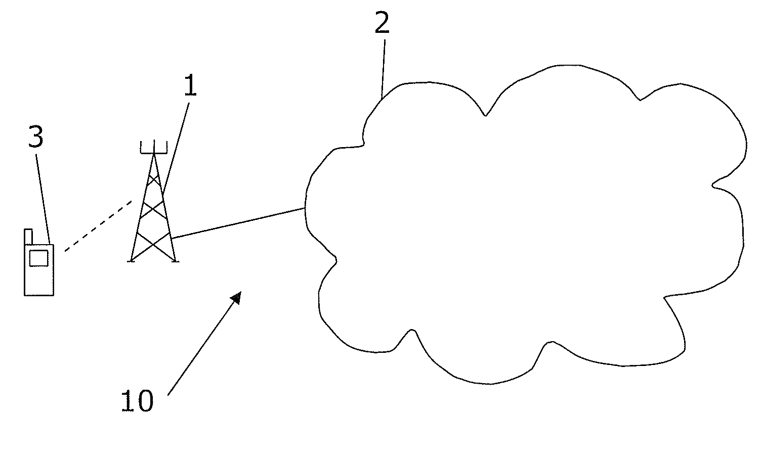
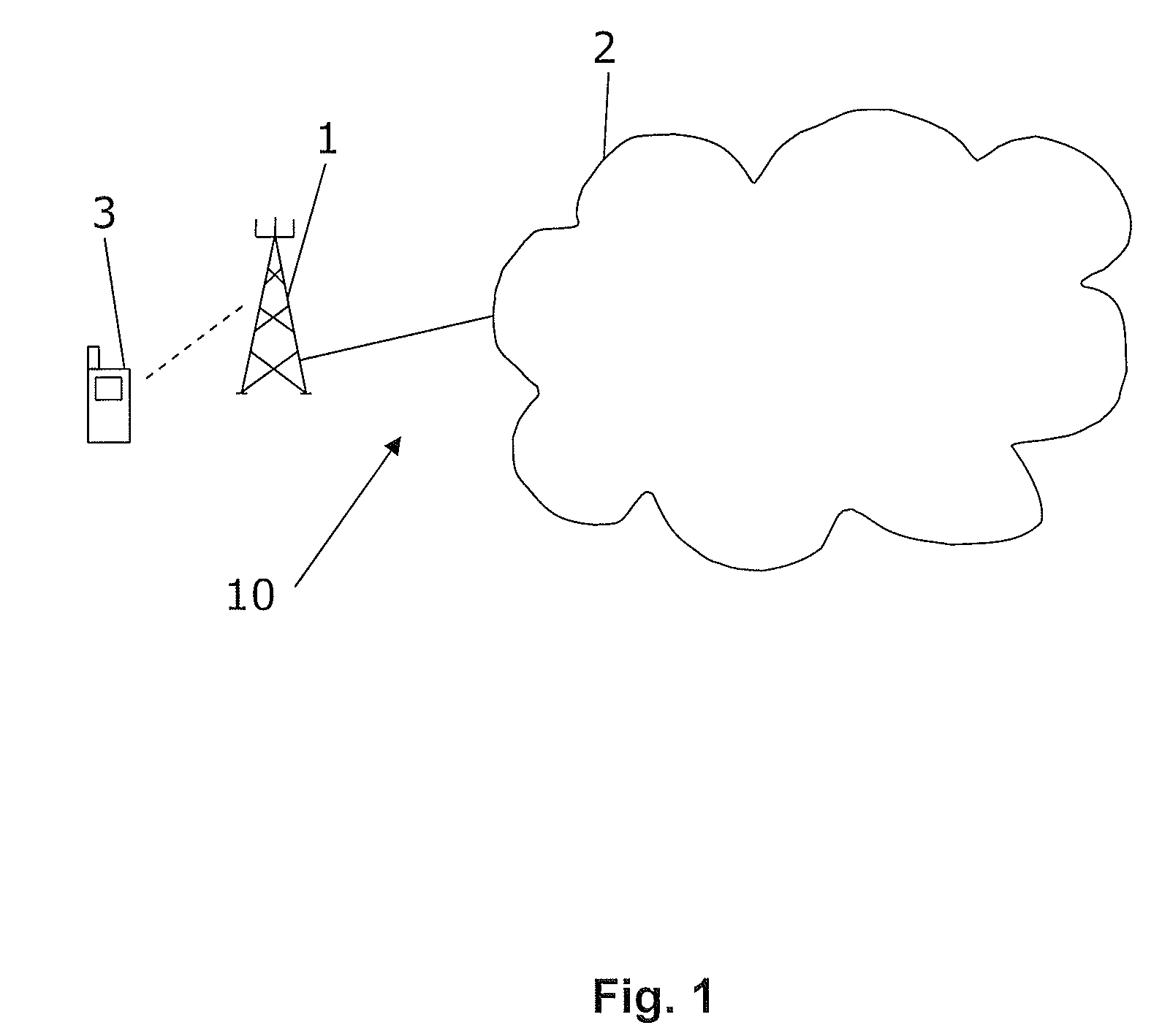
[0050]In FIG. 1 reference numeral 10 generally indicate a network according to the present invention, comprising at least one base station 1 or similar wireless network access node (e.g. access point or eNodeB) to an infrastructure communication network 2. The base station 1 is arranged to communicate with user equipment 3 (UE) wirelessly. The base station 1 may comprise one antenna or a plurality of antennas. The core infrastructure communication network 2 comprises several different entities depending on communication protocol used which will be discussed in more detail later in this document.
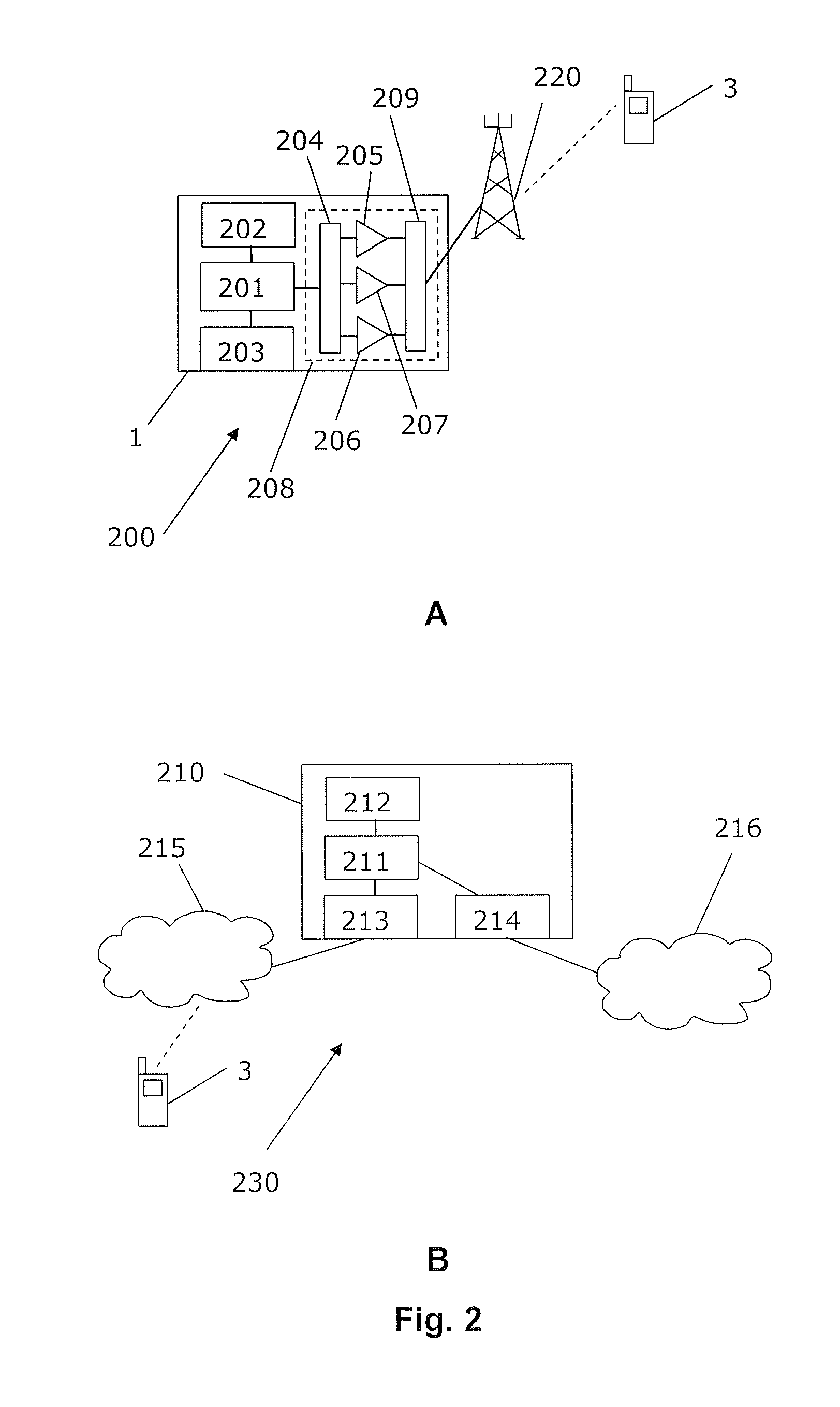
[0051]In FIG. 2A a network access node 1 implementing the solution according to the present invention is shown. The access node may comprise at least one processing unit 201, at least one memory unit 202, and at least one communication interface 203. Furthermore, the access node comprises a transceiver portion 208 for receiving and transmitting radio signals through an antenna 220. The transc...
PUM
 Abstract
Description
Claims
Application Information