
Heat dissipation apparatus

Inactive Publication Date: 2007-08-16
QUANTA COMPUTER INC
View PDF2 Cites 0 Cited by
  • Summary
  • Abstract
  • Description
  • Claims
  • Application Information

AI Technical Summary

Benefits of technology

[0010] It is therefore an aspect of the present invention to provide a heat dissipation apparatus to enhance the heat dissipation efficiency.
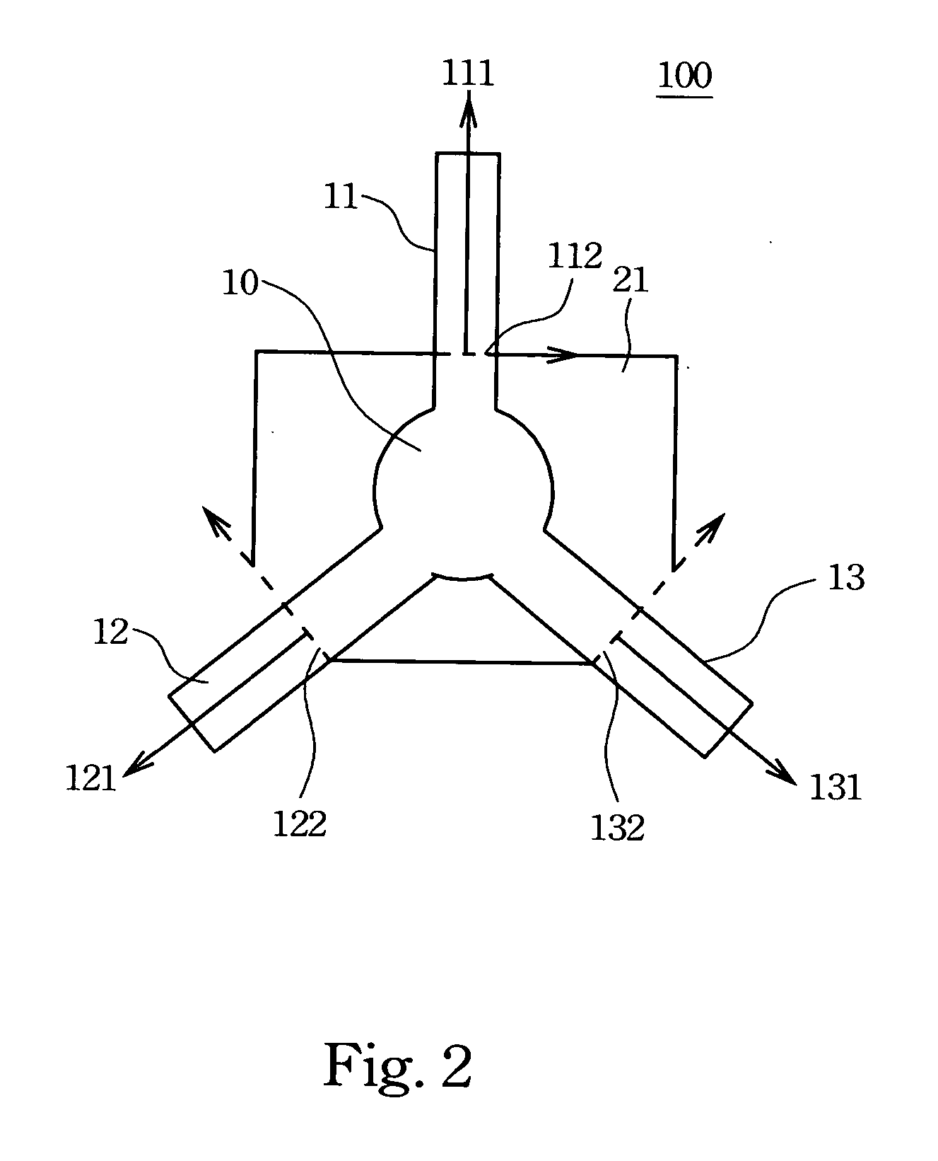
[0011] The heat dissipation apparatus comprises a heat sink and an angular shaped spring with multiple directional arms, wherein each of the directional arms extends in a corresponding direction to secure the heat sink, and the tangent directions of the contact boundary between the heat sink and the multi directional arms on the spring are perpendicular to the directions of the arm extensions. If the above tangents are indeed perpendicular to the direction of the spring arms, the force imposed from the spring on the heat sink would be uniform throughout the heat sink and the compactness of the contact area between the heat sink and the electronic component would be higher and the heat dissipation efficiency would increase hence lowering the risk of a system crash or damage due to overheating.

Problems solved by technology

If the temperatures are not lowered adequately, once the temperature is higher than the critical temperature, the electronic components would get damaged.
Therefore, if a spring is used to apply a force to a heat sink with a deformed shape, the compactness of the contact plane between the heat sink and the electronic component is low and is therefore not effective for lowering the temperature (the higher the compactness the better heat efficiency).

Method used


Image

  • Heat dissipation apparatus
  • Heat dissipation apparatus
  • Heat dissipation apparatus

Examples


Embodiment Construction

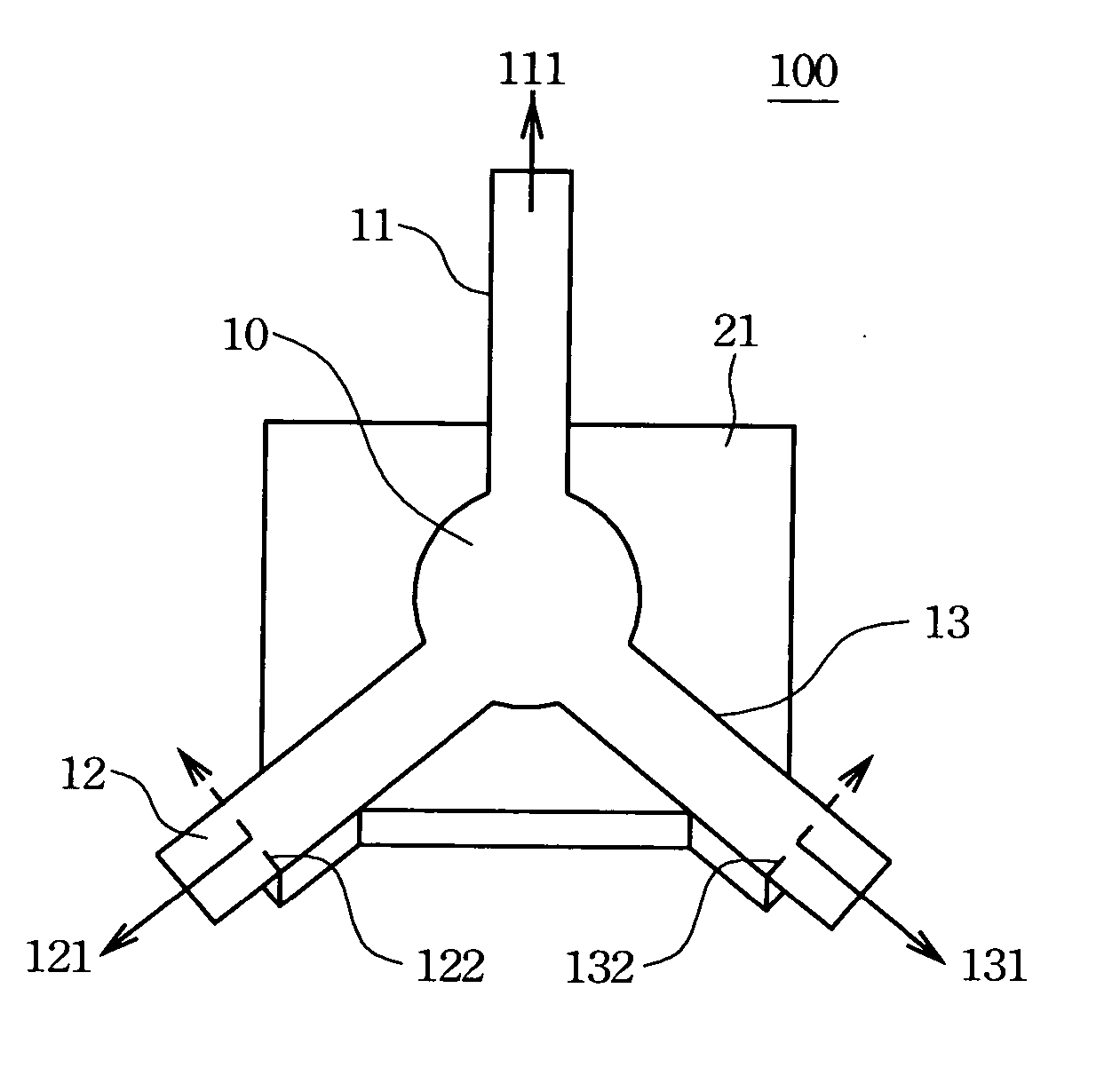
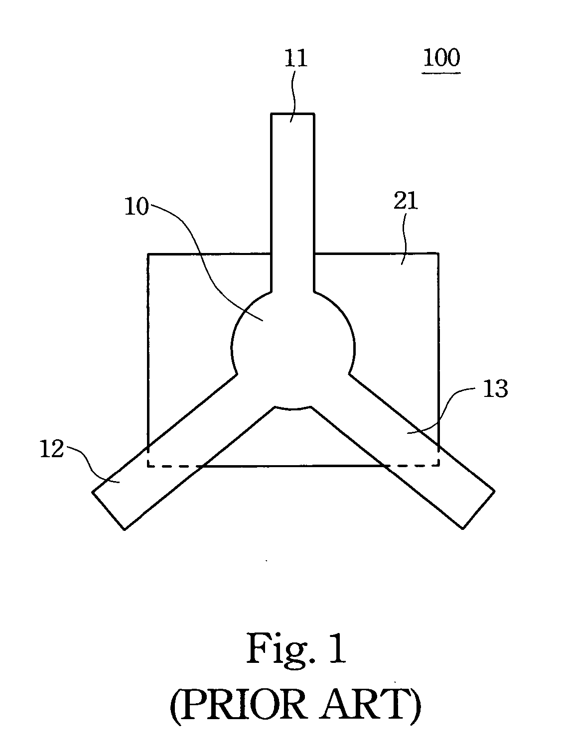
[0018]FIG. 2 is a schematic diagram of a heat dissipation apparatus in accordance with a preferred embodiment of the present invention. In FIG. 2, a triangular shaped spring 10 has three directional arms 11, 12 and 13 that extend in three corresponding directions 111, 121 and 131 and secure the heat sink 21. Tangent directions 122 and 132 of the contact boundary between the heat sink 21 and the directional arms 12 and 13 on the spring 10 are perpendicular to the corresponding directions 121 and 131, respectively. In the embodiment, the tangent direction 112 is originally perpendicular to the corresponding direction 111. The difference between FIG. 1 and FIG. 2 is that all the tangent directions 112, 122 and 132 in FIG. 2 are perpendicular to the corresponding directions 111, 121 and 131 respectively, whereas apart from the tangent direction for directional arm 11, the remaining tangent directions in FIG. 1 are not perpendicular to the directional arms 12 and 13. The advantage is tha...


PUM


Abstract

A heat dissipation apparatus used in a computer comprises a heat sink and an angularly shaped spring with multiple directional arms, wherein each of the directional arms extends in a corresponding direction and the tangent directions of the contact boundary between the heat sink and the multi directional arms on the spring are perpendicular to the corresponding directions. The force imposed from the spring on the heat sink is uniform as a result of the perpendicular mechanism, and therefore the heat dissipation efficiency is enhanced.

Description

RELATED APPLICATIONS [0001] The present application is based on, and claims priority from, Taiwan Application Serial Number 95202468, filed Feb. 13, 2006, the disclosure of which is hereby incorporated by reference herein in its entirety. BACKGROUND [0002] 1. Field of Invention [0003] The present invention relates to a heat dissipation apparatus. More particularly, the present invention relates to a heat dissipation capable of averaging the imposed force on the heat sink. [0004] 2. Description of Related Art [0005] To meet the demands of modern life, and progress in technology, electronic devices are increasingly able to provide more functions and services. For example, portable notebooks are a popular and successful product and not only because of the reasons stated above, but also because they are light and small in size. [0006] Most notebooks have a heat dissipation apparatus to lower the high temperatures generated by working electronic elements. If the temperatures are not lowe...

Claims


Application Information

Patent Timeline
IPC IPC(8): H05K7/20
CPCH01L23/4338H01L2924/0002H01L2924/00
Inventor CHANG, JUNG-WENLAI, CHUN-FENG
Owner QUANTA COMPUTER INC
Learn More