Heat exchanger

Inactive Publication Date: 2021-12-09
MAHLE INT GMBH
View PDF11 Cites 0 Cited by
  • Summary
  • Abstract
  • Description
  • Claims
  • Application Information

AI Technical Summary

Benefits of technology

[0006]It is therefore an object of the present invention to provide a heat exchanger having at least two r

Problems solved by technology

Such a heat exchanger design requires four manifolds and the manufacturing process is costly.
Such tubes and the fins between the tubes are difficult to assemble.

Method used


Image

  • Heat exchanger
  • Heat exchanger

Examples


Example

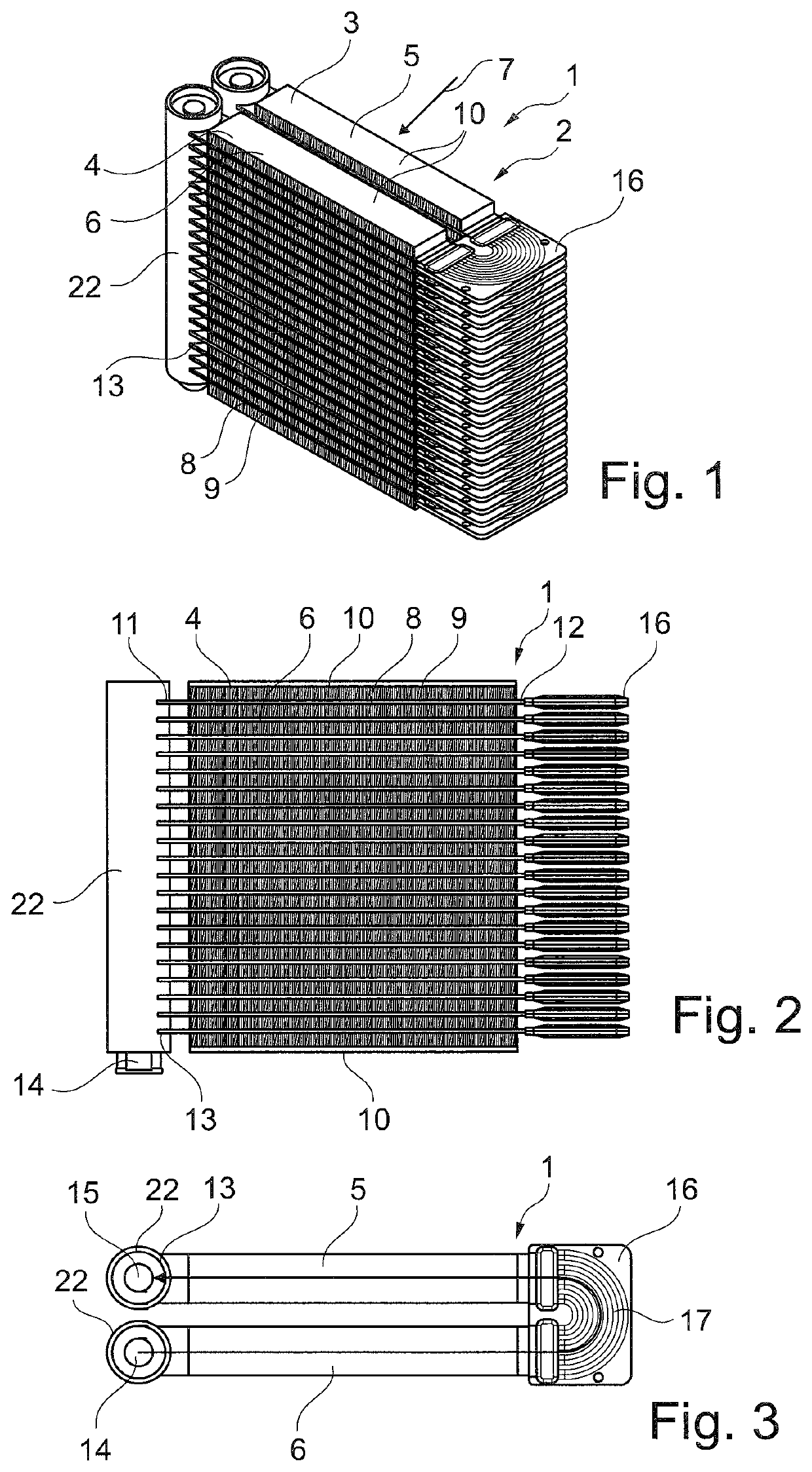
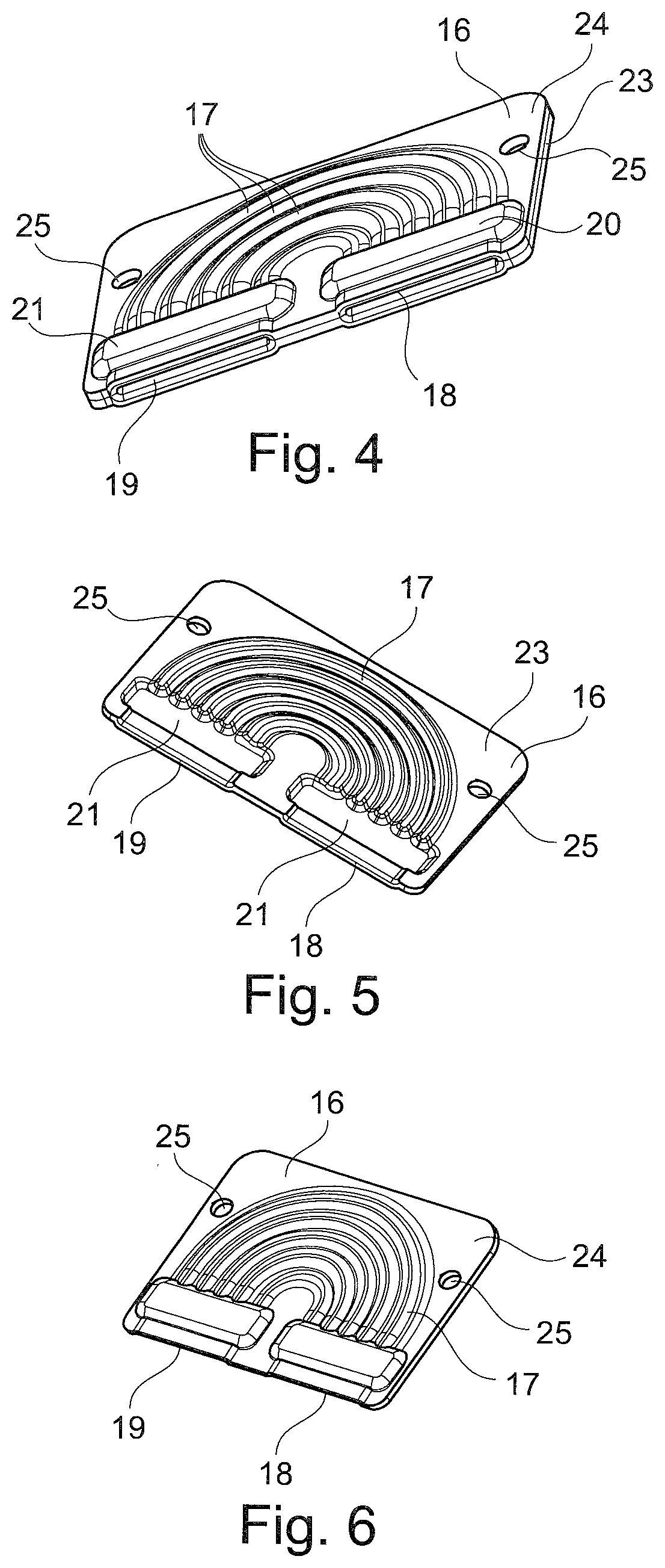
[0025]The FIGS. 1 to 3 show different views of an embodiment of a heat exchanger 1.

[0026]The heat exchanger 1 is in this shown embodiment a heat exchanger of a refrigerant cycle of the air-conditioning system of a motor vehicle or for residential and / or commercial application, e.g. for the use for residential or non-residential buildings etc. The heat exchanger may be e.g. an evaporator or a condenser.

[0027]Nevertheless the heat exchanger 1 might be another heat exchanger e.g. of a cooling cycle of a motor vehicle or of a residential or commercial application, like a heater core, a radiator or something different like an oil cooler or the like.

[0028]The heat exchanger 1 is a two-row heat exchanger having a heat exchanger core 2 having two rows 3, 4 of tube and fin blocks 5, 6.

[0029]A first tube and fin block 5 is provided and additionally a second tube and fin block 6 is provided which are arranged just adjacent to each other and which are approached by an air flow 7 one after the o...


PUM


Abstract

A heat exchanger having a heat exchanger core having at least two rows of tube and fin blocks, each tube and fin block contains an assembly of tubes and fins, wherein the tubes are aligned parallel to each other while the fins are located between adjacent tubes, each tube having a first tube end and a second tube end, each tube and fin block of the first tube and fin block and the second tube and fin block having a manifold tube, the manifold tubes having a row of openings for a fluid tight connection with tubes of a tube and fin block, wherein the first tube ends of the first tube and fin block are fluid tight connected to the openings of a first manifold and the first tube ends of the second tube and fin block are fluid tight connected to the openings of a second manifold.

Description

BACKGROUND OF THE INVENTIONField of the Invention[0001]The present invention relates to a heat exchanger, especially for a refrigeration cycle of a motor vehicle or for residential and / or commercial application.Description of the Background Art[0002]Two row heat exchangers are known in the prior art. Such two row heat exchangers are known as evaporators having two heat exchanger cores which are located in two rows and which are aligned in air flow direction one behind the other such that the air flow crosses first one of the two heat exchanger cores and then the other of the two heat exchanger cores.[0003]It is known that the two heat exchanger cores are produced with two manifolds with a row of tubes and fins between the two manifolds such that each tube is inserted with one of his tube ends in an opening of one of the two manifolds and with the other tube end in an opening of the other manifold. Such heat exchanger cores are fluidically connected by connection tubes. Such a heat e...

Claims


Application Information

Patent Timeline
IPC IPC(8): F25B39/02F28F1/32
CPCF25B39/02F28D2021/0085F28F2215/12F28F1/325F25B39/04F28D1/0476F28D1/05391F28F3/12F28F2009/0295F28F1/126F28F2275/04
Inventor DITTLY, BRUCE WILLIAM
Owner MAHLE INT GMBH
Why Eureka
Try Eureka