Stent positioning

Pending Publication Date: 2021-08-19
KONINKLJIJKE PHILIPS NV
View PDF0 Cites 0 Cited by
  • Summary
  • Abstract
  • Description
  • Claims
  • Application Information

AI Technical Summary

Benefits of technology

[0007]As an advantage, the detection of the device position markers is provided only for a selected part of the image of the region of interest. The selected part can then be subject to a more detailed search, resulting in an increased accuracy as well as a

Problems solved by technology

However, it has been shown that even device marker detection can be cumbersome, for example

Method used


Image

  • Stent positioning
  • Stent positioning
  • Stent positioning

Examples


Example

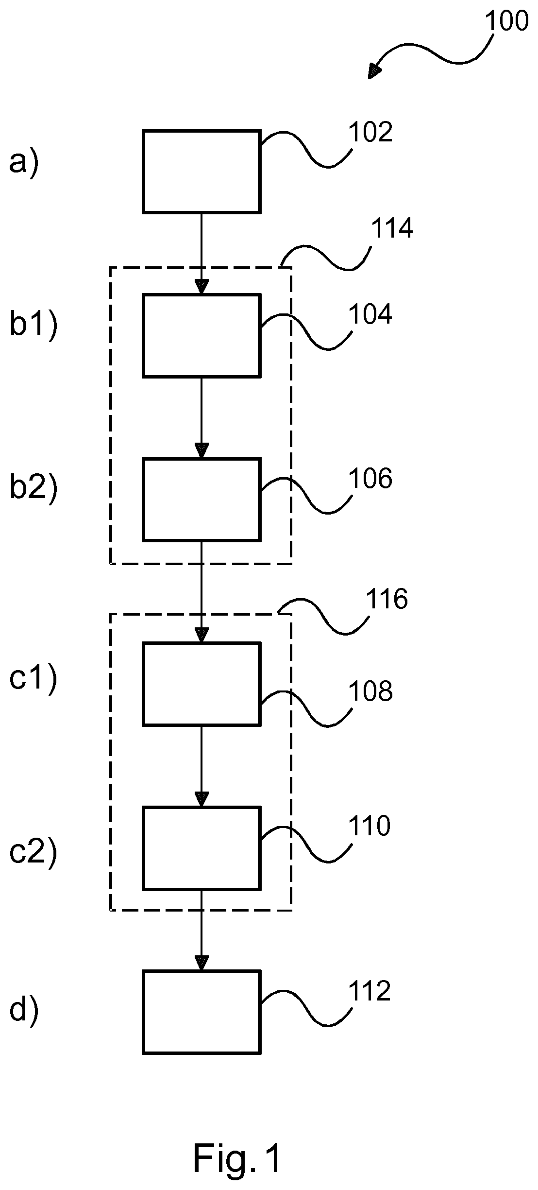
[0042]In FIG. 1, an example of a method 100 for positioning a medical interventional device is shown. The method 100 comprises the following steps:[0043]In a first step 102, also referred to as step a), at least one image of a region of interest of a subject is provided. In the at least one image, at least a part of a guiding apparatus for the medical interventional device is arranged in the region of interest, which part of the guiding apparatus comprises at least one apparatus position marker visible in the at least one image. Further, in the at least one image, a medical interventional device is arranged at least partly in the region of interest, which medical interventional device comprises device position markers, which are less visible in the image than the at least one guiding apparatus marker.[0044]In a second step 104, also referred to as step b1), the at least one apparatus position marker is detected in the at least one image.[0045]In a third step 106, also referred to as...


PUM


Abstract

The present invention relates to positioning of stents or other medical interventional devices. In order to provide an improved marker detection suitable for smaller markers, a device (10) for positioning a medical interventional device is provided. The device comprises a data input interface (12), a data processing unit (14) and a data output interface (16). The data input interface is configured to provide at least one image of a region of interest of a subject. In the at least one image, at least a part of a guiding apparatus for a medical interventional device is arranged in the region of interest, which part of the guiding apparatus comprises at least one apparatus position marker visible in the at least one image. Further, in the at least one image, a medical interventional device is arranged at least partly in the region of interest, which medical interventional device comprises device position markers, which are less visible in the image than the at least one apparatus position marker. The data processing unit is configured to detect the at least one apparatus position marker in the at least one image, and to define a proximity region in the at least one image based on the at least one apparatus position marker, and to select the proximity region, to detect the device position markers in the proximity region, and to enhance the device position markers in the at least one image for supporting a positioning of the medical interventional device. The data output interface is configured to provide the at least one image with the enhanced device position markers.

Description

FIELD OF THE INVENTION[0001]The present invention relates to positioning of stents or other medical interventional devices, and relates, in particular, to a device for positioning a medical interventional device, to a medical imaging system and to a method for positioning a medical interventional device, e.g. a stent, as well as to a computer program element for controlling an apparatus and a computer readable medium having stored the program element.BACKGROUND OF THE INVENTION[0002]In minimal invasive surgery, it is known to insert medical interventional devices like stents or other forms or prosthesis in a lumen, e.g. a vasculature or tissue structure of a subject, via a guiding apparatus like a guidewire. For correct placement of the medical interventional devices, the relative position of the medical interventional device must be determined. For this purpose, the current position of the device is determined and brought into relation to the subject. An example of a current positi...

Claims


Application Information

Patent Timeline
IPC IPC(8): A61F2/958A61B6/00A61B90/00
CPCA61F2/958A61B6/469A61B2090/3966A61B6/487A61B2090/3983A61B90/39G06T7/73G06T2207/10121G06T2207/30052G06T2207/30204A61B6/504
Inventor AUVRAY, VINCENT MAURICE ANDREFLORENT, RAOUL
Owner KONINKLJIJKE PHILIPS NV
Why Eureka
Try Eureka