Lateral sealing gasket and method

a gasket and lateral technology, applied in the field of three-part gasket systems, can solve the problems of increasing the overall weight and cost, affecting the sealing effect, and the technique, while effective, may be considered expensive and not suitable for all applications, and achieve the effect of enhancing the contact pressure of the beads

Inactive Publication Date: 2010-10-28
FEDERAL MOGUL WORLD WIDE
View PDF26 Cites 44 Cited by
  • Summary
  • Abstract
  • Description
  • Claims
  • Application Information

AI Technical Summary

Benefits of technology

[0010]According to a second aspect of the invention, a three-part gasket system is provided for sealing a pair of opposing flanges together against the passage of liquid without compressing the flanges together. The three-part system consists of an elongated elastomeric body, along with first and second flanges. The elongated elastomeric gasket body defines a generally continuous length. The first and second flanges extend parallel to the gasket body, and each have a pair of oppositely facing contact faces. The gasket body includes an integral first sealing member extending laterally toward the first flange, and an integral second sealing member extending laterally toward the second flange. Each of the first and second sealing members extend continuously and uninterrupted along the length of the gasket body. A first pair of opposing beads protrudes laterally from the first sealing member. The first opposing pair of beads extends continuously and uninterrupted along the length for establishing laterally directed contact seals against the respective contact faces of the first flange. Likewise, the second pair of opposing beads is similarly structured and establishes a laterally directed contact seal against the respective contact faces of the second flange. An elongated reinforcing spring is embedded within the gasket body and extends within each of the first and second sealing members. The reinforcing spring has at least one U-shaped bend for continuously urging the respective first and second pairs of beads laterally relative to the length so as to enhance the contact pressure of the beads against the respective contact faces of the first and second flanges. The gasket maintains a liquid impervious seal between the first and second flanges through self-generated lateral contact pressure on each of the respective contact faces.

Problems solved by technology

As a result, the flange members tend to be heavily constructed, thereby adding to overall weight and cost.
This technique, while effective, may be considered expensive and not suited for all applications.

Method used


Image

  • Lateral sealing gasket and method
  • Lateral sealing gasket and method
  • Lateral sealing gasket and method

Examples


Embodiment Construction

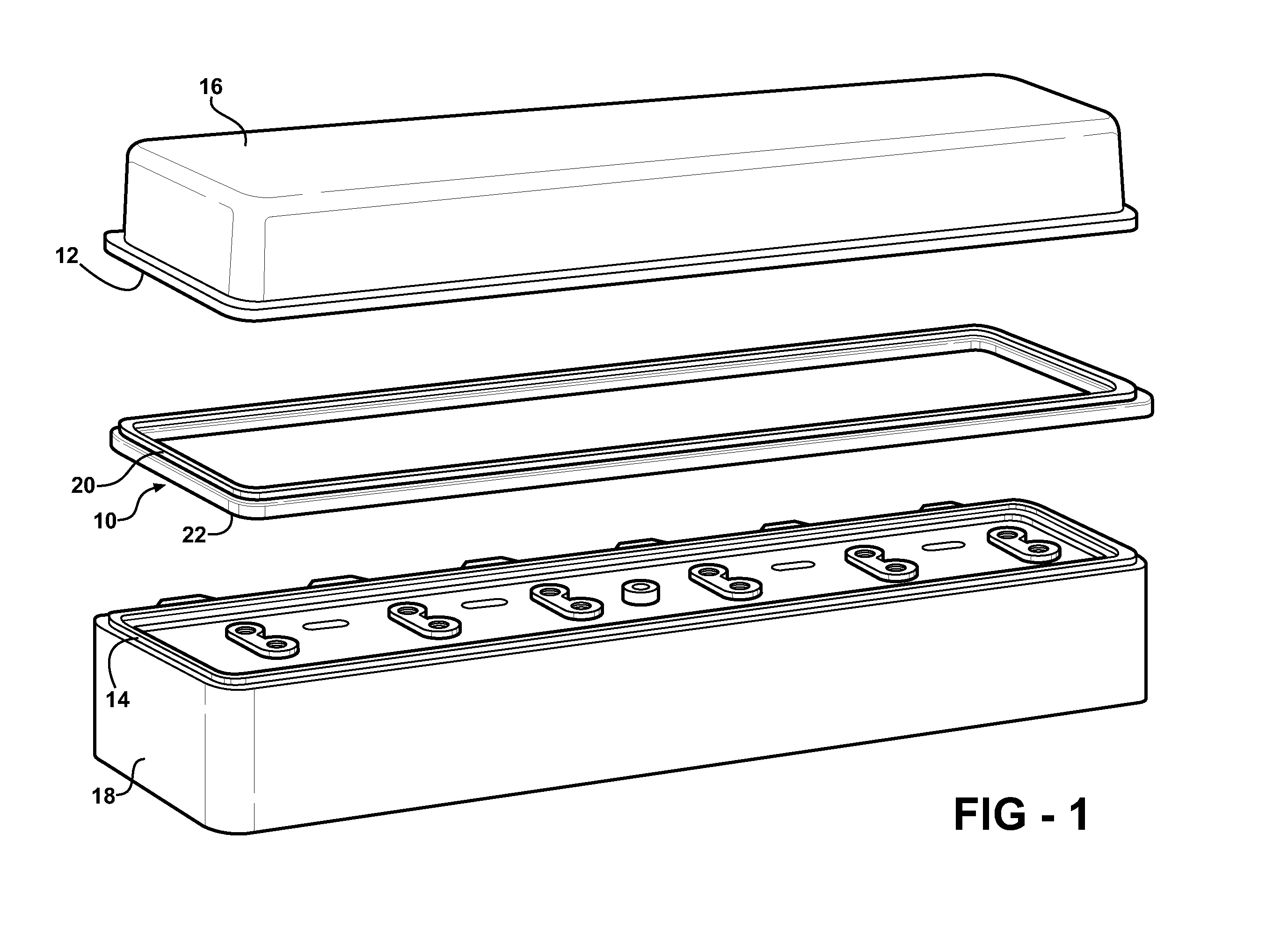
[0022]Referring to the Figures, wherein like numerals indicate like or corresponding parts throughout the several views, a sealing assembly according to the subject invention is exemplified in FIG. 1 comprising a gasket, generally indicated at 10, interposed between a first flange 12 and a second flange 14. Although a gasket assembly according to this invention may find usefulness in a variety of applications, the exemplary embodiment described here portrays use in an automotive environment where the first flange 12 comprises the lower, peripheral edge of a valve or rocker cover 16. The second flange 14 is here shown forming the upper peripheral edge of a cylinder head 18. Of course, these specifically-named components are merely examples, and those of skill in the art will appreciate other components, both within and outside of the field of vehicular engines, with which to apply the teachings of this invention.

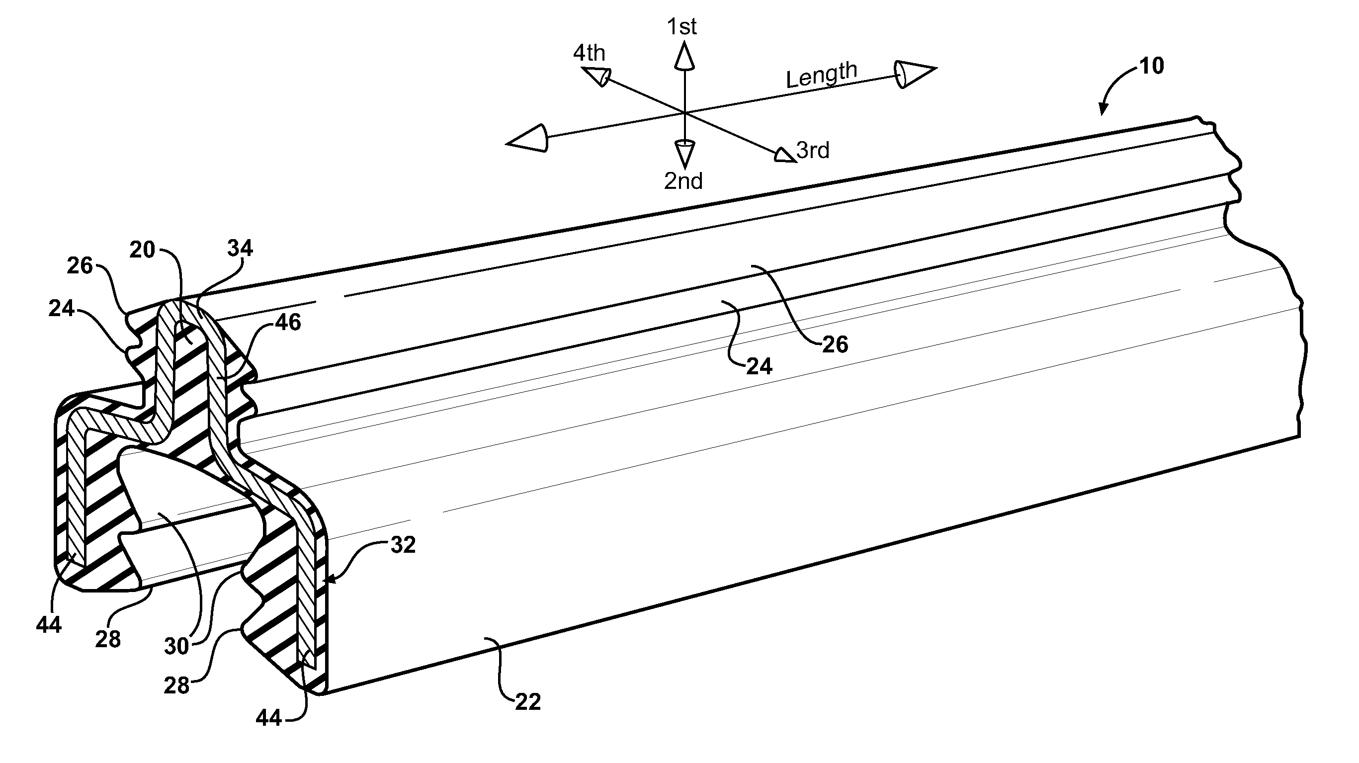
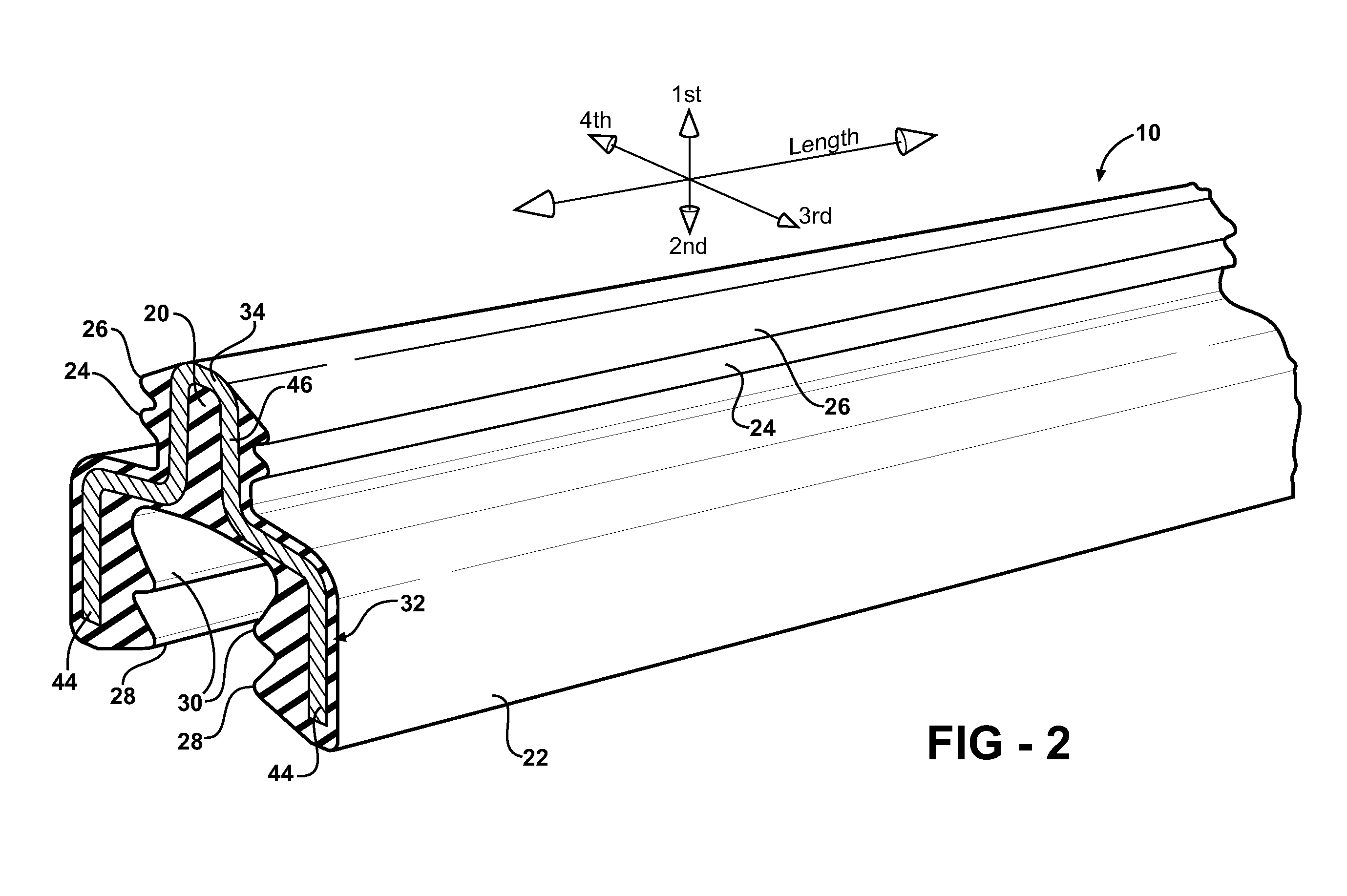
[0023]The gasket 10 as depicted in FIG. 1 is formed as a continuous, i.e...


PUM


Abstract

An elongated elastomeric gasket (10) seals a pair of opposing flanges (12, 14) against the passage of liquid without compressing the flanges (12, 14) together. A reinforcing spring (32) is embedded within the elastomeric gasket (10) and is shaped so as to react when deflected by the operation of installing the gasket (10) into an operative position between the flanges (12, 14). A strategically located U-shaped bend (34) formed in the reinforcing spring (32) causes, in a preferred embodiment, contact pressure to be increased between opposed sealing beads at the other end of the gasket. More specifically, lateral contact pressure between a first pair of sealing beads (24) and their associated contact faces (38) is increased as a direct result of the reinforcing spring (32) being displaced during the assembly process. Likewise, lateral contact pressure between a second pair of beads (28) and their respective contact faces (42) is increased in direct response to the lateral displacement of the reinforcing spring (32) in the region of the first beads (24) during assembly.

Description

CROSS REFERENCE TO RELATED APPLICATIONS[0001]This application is a Divisional of U.S. patent application Ser. No. 11 / 839,056 filed Aug. 15, 2007, now U.S. Pat. No.______.BACKGROUND OF THE INVENTION[0002]1. Field of the Invention[0003]A three-part gasket system for sealing opposing flanges without compressing the flanges together, and more particularly a loose-piece gasket that maintains a liquid impervious seal through self-generated lateral contact pressure exerted on each of the opposing flanges.[0004]2. Related Art[0005]Gaskets are used in a wide variety of sealing applications. Typically, the gasket is compressed between opposing flanges to perfect a fluid impervious seal. The compression load is usually accomplished by spacing a plurality of bolts or other fastening devices around the gasket. For practical purposes, both the gasket and the opposing flanges must be designed and constructed out of sufficiently sturdy material so as to support the compression loads necessary to pe...

Claims


Application Information

Patent Timeline
Patent Type & Authority Applications(United States)
IPC IPC(8): F16J15/02
CPCF16J15/125F16J15/121
Inventor HURLBERT, DAVIDWATERS, ROB
Owner FEDERAL MOGUL WORLD WIDE
Why Eureka
Try Eureka