Pair of progressive power lens and method for designing same

a technology of progressive power lenses and power lenses, applied in the field of progressive power lenses, can solve the problems of extreme binocular vision functions of right and left eyes, wearers to feel distortion or sway of images, and inconvenience of binocular vision in intermediate vision,

Active Publication Date: 2010-10-28
HOYA CORP
View PDF1 Cites 34 Cited by
  • Summary
  • Abstract
  • Description
  • Claims
  • Application Information

AI Technical Summary

Benefits of technology

[0027]As described above, among conventional techniques, there has not been disclosed a technique to reduce or eliminate the inconvenience of spectacles with right and left progressive power lenses having different distance dioptric powers in the binocular vision function of a wearer.
[0028]Fundamentally, a binocular vision function means an advanced function such as simultaneous vision, stereoscopic vision, or fusion, possessed by a visual system including the brain, and is not a function possessed by spectacles or lenses of spectacles. However, all these functions such as simultaneous vision, stereoscopic vision, and fusion are based on the premise of good binocular vision, and it is obvious that the use of spectacles to impede binocular vision results in impairing the binocular vision function. Accordingly, by providing spectacles that impede the binocular vision less, the original binocular vision function possessed by the visual system of a spectacle wearer can be sufficiently exerted.
[0029]In view of the above problems, it is an object of the present invention to provide a pair of progressive power lenses in which the inconvenience in the binocular vision function is reduced when wearing and using spectacles that use right and left progressive power lenses having different distance dioptric powers, and a method for designing the same.
[0039]Then, as an index of the ratio, a ratio of displacement amounts of the line of sight on the right and left progressive power lenses is used. In a case of using a lens of reference dioptric power, a ratio of the amounts of displacement of the lines of sight in the lens of the reference dioptric power and the right and left progressive power lenses of prescribed dioptric power is utilized. Then, by modifying the average dioptric power distribution and the astigmatism distribution of each progressive power lens based on this ratio, the optical situation at positions on the lenses through which the lines of sight of the both eyes pass, that is, the average dioptric power distribution and the astigmatism distribution can be brought closer to each other. This allows the reduction of the degree of impairing the binocular vision function of a wearer.
[0040]That is, according to the method for designing a pair of progressive power lenses of the present invention, in a case of preparing spectacles of progressive power lenses for a patient having a dioptric power difference between the prescribed dioptric powers of the right and left eyes, it is possible to provide a method for designing a pair of progressive power lenses that reduces the inconvenience in the binocular vision function caused by the dioptric power difference.

Problems solved by technology

However, it is widely known that it presents disadvantages specific to the progressive power lens such that due to the necessity of arrangement of a plurality of visual fields such as a field for looking far, a field for looking near, and a field for looking at a distance intermediate therebetween, without a boundary line existing within a limited lens area, each visual field is not always sufficiently wide, and that there is a region mainly in a side visual field which causes the wearer to feel distortion or sway of an image.
Although many related arts have been proposed to improve these disadvantages, most of the related arts are related to designing techniques to give more preferred average dioptric power distribution or aberration distribution depending on the individual prescribed dioptric power and the wear state, and those focusing on the combination of right and left lenses and aiming for the improvement of a binocular vision function of right and left eyes are extremely scarce.
In the above-described conventional technique, there are disadvantages, that a boundary line (ridge line of bending surfaces) of two types of intersecting surfaces is generated at the border between the distant and close regions of a lens subjected to a cutoff processing, thereby being distinct and that a jump of an image, referred to as an image jump, is generated as a result of an abrupt change in the prismatic effect at the boundary line as a border.
However, since the right and left addition powers in the middle of the progressive corridors are different in this method, there is a problem of the occurrence of the inconvenience for a binocular vision in intermediate vision.
However, in the former method of slab-off to generate a boundary line, “continuity of visual field” is lost, which is extremely important for progressive power lenses.
In addition, in the latter method of changing the dioptric power in the progressive corridors described in Patent Document 1, although the “continuity of visual field” is maintained, the intermediate visual field viewed through the progressive corridors is damaged.
However, these related arts only classify the changes in the passing positions of the line of sight in near vision extremely simply and cope with them, which cannot be sufficient improvement.
For example, the related arts, such as “ergonomic inset” and “variable inset”, cope only with horizontal positional shifting and do not cope with vertical positional shifting.
Moreover, these related arts propose only the position alignment of near visual fields of the right and left eyes, and there is no conventional technique that proposes an improvement of a binocular visual field in all visual field regions of progressive power lenses, such as distant vision, side vision, near vision, and intermediate vision.
Further, although there are generally known techniques to, for example, align curves and thicknesses on the front side of the right and left lenses with each other in a case where the difference of dioptric power is present, they are neither the techniques to disclose an improvement of binocular visual fields of all visual field regions in progressive power lenses such as distant vision, side vision, near vision, and intermediate vision, in the configuration of the progressive power lenses described above, nor the techniques to propose configurations of an average dioptric power distribution and an astigmatism distribution for a binocular vision.

Method used


Image

  • Pair of progressive power lens and method for designing same
  • Pair of progressive power lens and method for designing same
  • Pair of progressive power lens and method for designing same

Examples


first embodiment

[1] First Embodiment

[0105]First, a description will be given to Examples 1 to 3 as examples of not including cylindrical dioptric power in the distance dioptric power as a first embodiment of the present invention.

[0106]Table 1 is a list showing right and left distance dioptric powers and results of obtaining a ratio of amounts of displacement of lines of sight caused by the power difference thereof in Example 1 to Example 3 of the present invention.

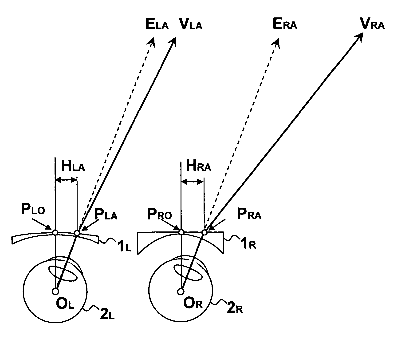
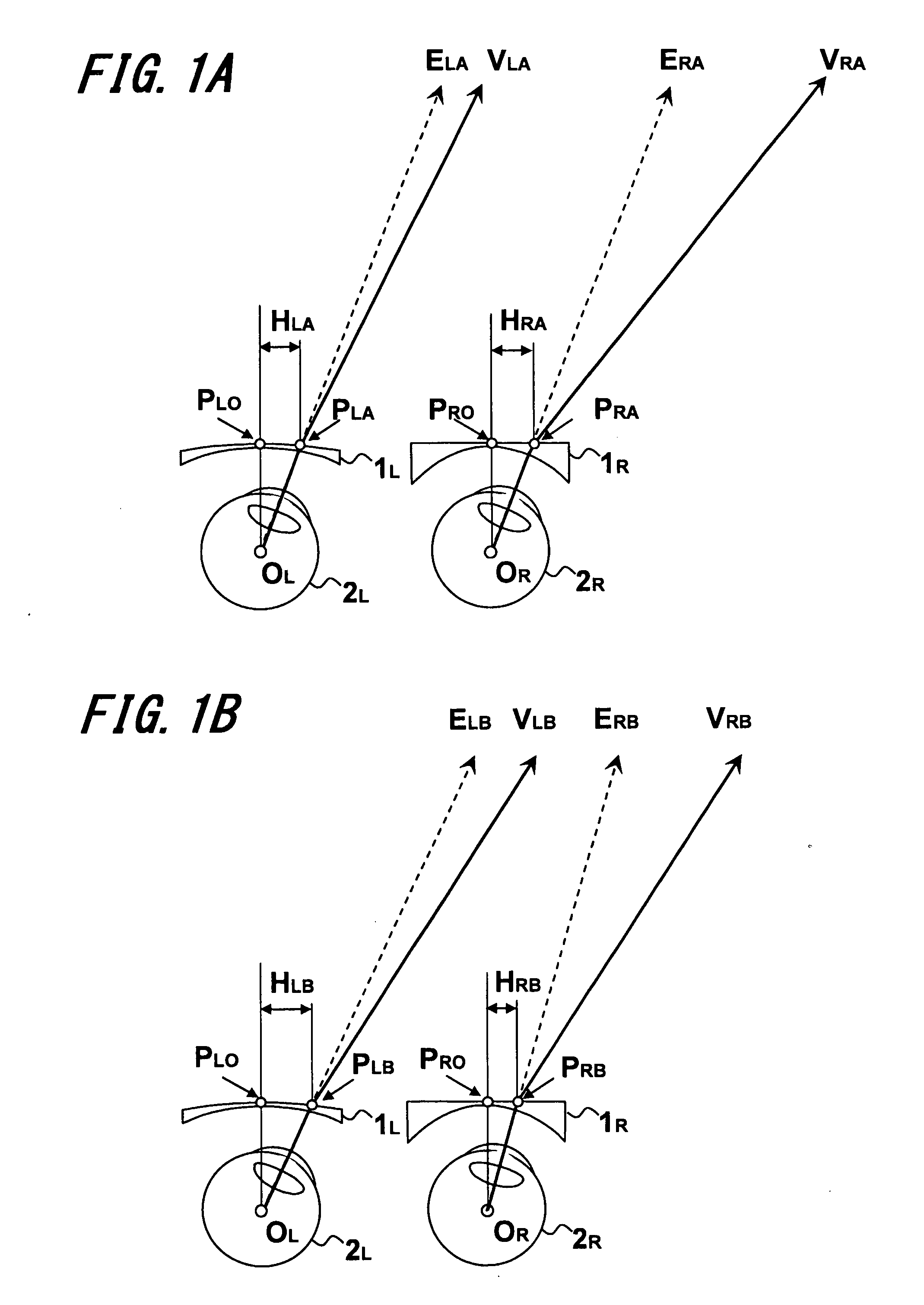
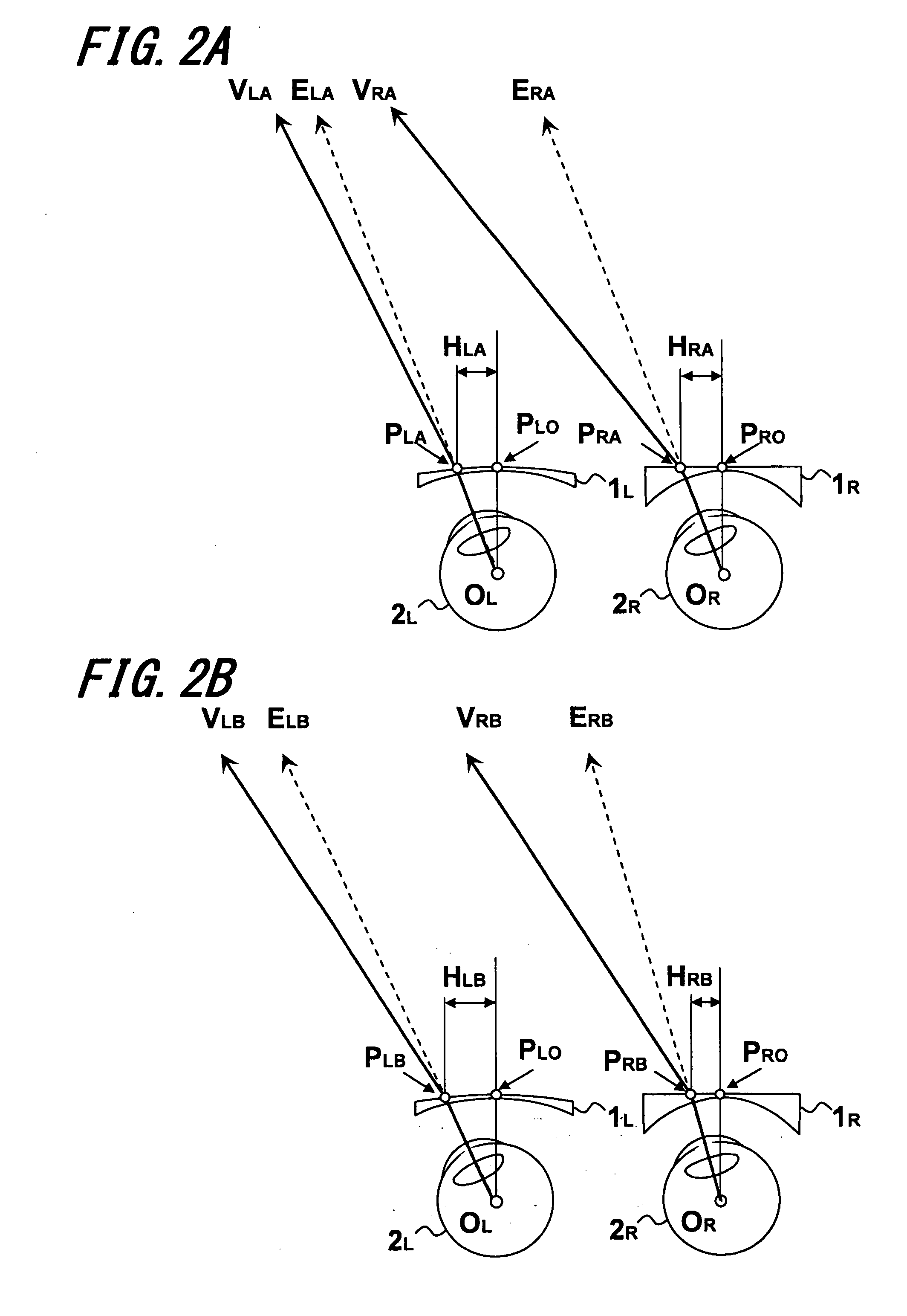
[0107]The reference characters and indications in Table will be described. It should be noted that the reference characters shown in FIGS. 1B, 2B . . . and 8B illustrating situations in which a person who wears spectacles is actually forced to converge, diverge, or the like are used for the reference characters described below.

[0108]A reference character DL means left distance dioptric power (dioptre), a reference character DR means right distance dioptric power (dioptre), and a reference character DC means reference dioptric power (diop...

example 1

(1) Example 1

[0115]As shown in Table 1, Example 1 is progressive power lenses having distance dioptric power for the right eye with more minus dioptric power compared with the left eye.

[0116]FIG. 1B is a diagram of a situation where a person who wears the pair of progressive power lenses of Example 1 views a side on the right in the distance with both eyes, viewed from overhead of the wearer.

[0117]The situation is as described above, and a state is illustrated in which the wearer viewing a distance is forced to converge in spite of not being accompanied by accommodation strain.

[0118]Here, a description will be given to a method for calculating the “adjustment ratios” required to correct the design (average dioptric power distribution and astigmatism distribution) of the progressive power lenses in conventional techniques according to the present invention.

[0119]A method is shown as an example in which a relational expression of the amount HLB of left eye displacement and the amount ...

example 2

(2) Example 2

[0186]Example 2 is an example using a design approach similar to Example 1, in which the progressive power lens for the right eye has a stronger minus dioptric power than that for the left eye.


PUM


Abstract

An object is to reduce the inconvenience given to the binocular vision function when wearing and using spectacles making use of a pair of progressive power lenses having different distance dioptric power for right and left. For this reason, the present invention associates, in a pair of progressive power lenses corresponding to the right and left eyes, an average dioptric power distribution and an astigmatism distribution determined from prescribed dioptric power and a wear state of one of the progressive power lenses with an average dioptric power distribution and an astigmatism distribution determined from prescribed dioptric power and a wear state of the other progressive power lens, and thereby average dioptric power distributions and astigmatism distributions of the respective progressive power lenses are changed.6

Description

TECHNICAL FIELD [0001]The present invention relates to a pair of progressive (refractive) power lenses with continuously varying (refractive) power in a multifocal spectacle lens having addition power to compensate for lack of power of accommodation in presbyopia, and a method for designing the same.BACKGROUND ART [0002]A progressive power lens is widely used in general because of an advantage that in appearance it is hardly detected from others as a spectacle for the aged in spite of a spectacle lens for presbyopia, an advantage that it allows a wearer to clearly look continuously from a far distance to a near distance without discontinuity, and so on. However, it is widely known that it presents disadvantages specific to the progressive power lens such that due to the necessity of arrangement of a plurality of visual fields such as a field for looking far, a field for looking near, and a field for looking at a distance intermediate therebetween, without a boundary line existing wi...

Claims


Application Information

Patent Timeline
Patent Type & Authority Applications(United States)
IPC IPC(8): G02C7/06
CPCG02C7/025G02C7/027G02C7/068G02C7/061G02C7/028
Inventor KITANI, AKIRAHATANAKA, TAKASHIKIKUCHI, YOSHIHIROQI, HUA
Owner HOYA CORP
Why Eureka
Try Eureka