
Stress-based Topology Optimization Method and Tool

Inactive Publication Date: 2010-10-28
CATERPILLAR INC
View PDF3 Cites 19 Cited by
  • Summary
  • Abstract
  • Description
  • Claims
  • Application Information

AI Technical Summary

Benefits of technology

[0013]In yet another aspect of the present disclosure, a computer program product is provided. The computer program may include a computer-readable medium with control logic stored therein for configuring a computer to perform stress-based topology optimization. The control logic may includ

Problems solved by technology

However, because nonlinear programming algorithms cannot identify such regions, they tend to converge to locally optimal designs.
The second challenge of stress-based topology optimization pertains to the local nature of stress constraints.
Although finite, the number of such material points is still too large for practical applications.
While such global approaches are computationally efficient, they do not adequately control the local stress behaviors.
The third challenge associated with stress-based topology optimization pertains to the highly nonlinear dependence of stress constraints on the structure or design in question.
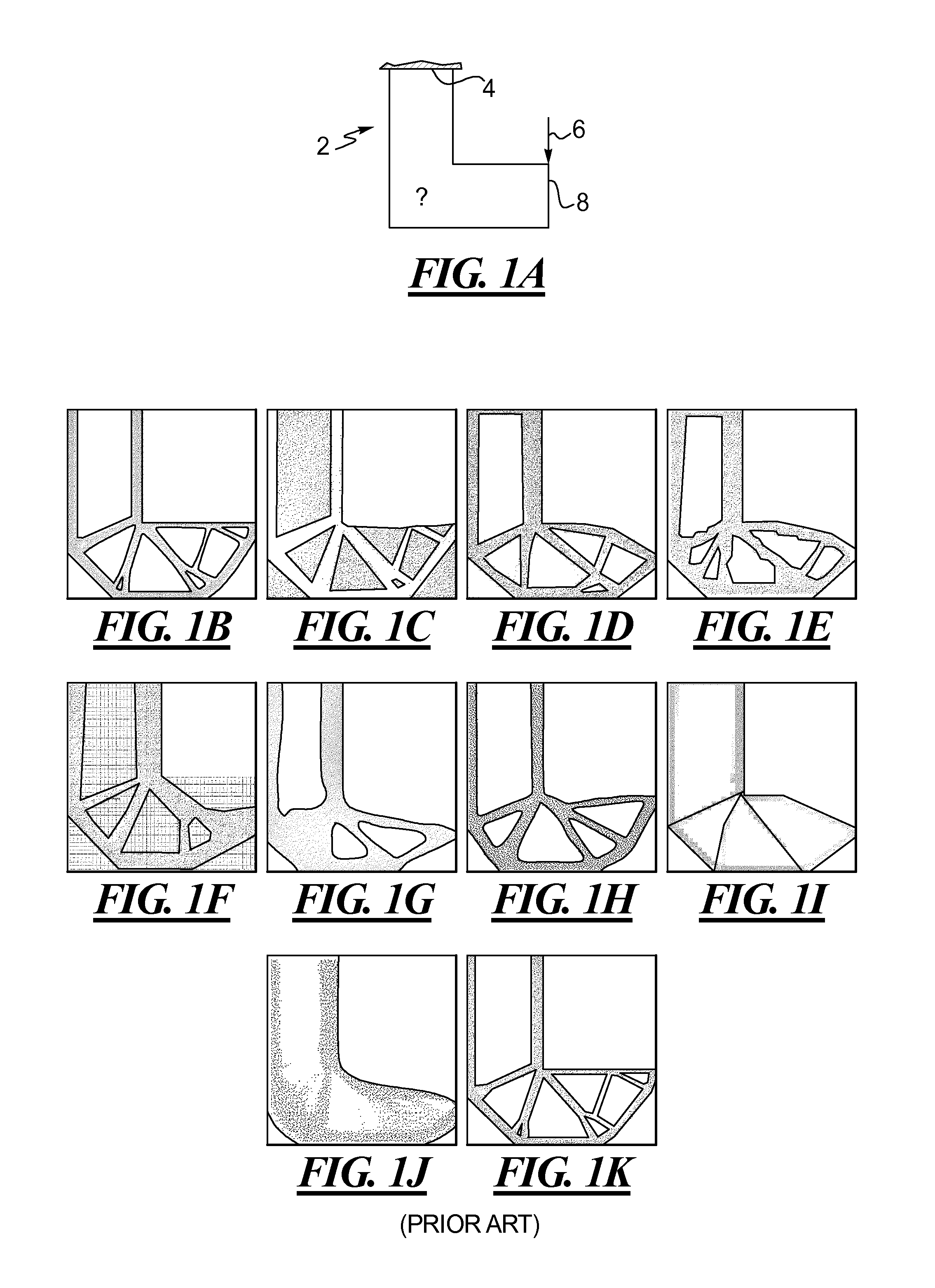
In the designs shown, the design of FIG. 1F is obtained via an integer programming method which is not viable for large scale applications.
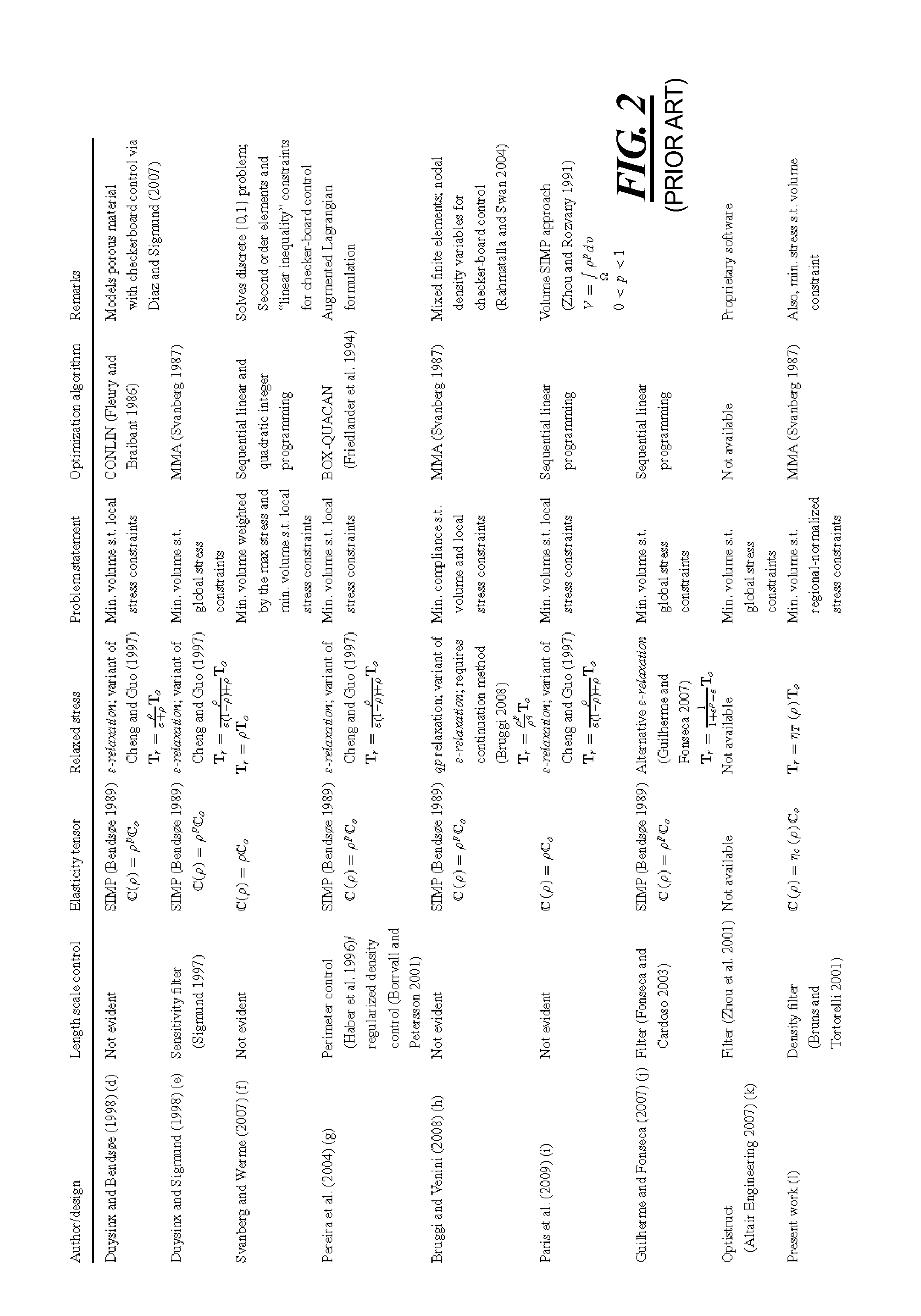
The designs of FIGS. 1F and 1H do not contain length scale control but rather checkerboard control, and hence, their problem formulations are most likely ill-posed.
The design of FIG. 1J undesirably contains excessively large regions of gray material.
However, the design of FIG. 1G requires significant tuning of parameters which can heavily influence the final topology, and further, entail significant computational expenses which outweigh the benefits of solving the problem definition in question.
While the local stress measurement approach provides precise control of a stress field, it is prohibitively expensive to employ in practical applications.
Furthermore, while the global stress measurement approach is more computationally efficient, its control of the stress field is not as precise, resulting in designs that are less than optimal and in violation of stress constraints.

Method used


Image

  • Stress-based Topology Optimization Method and Tool
  • Stress-based Topology Optimization Method and Tool
  • Stress-based Topology Optimization Method and Tool

Examples


Embodiment Construction

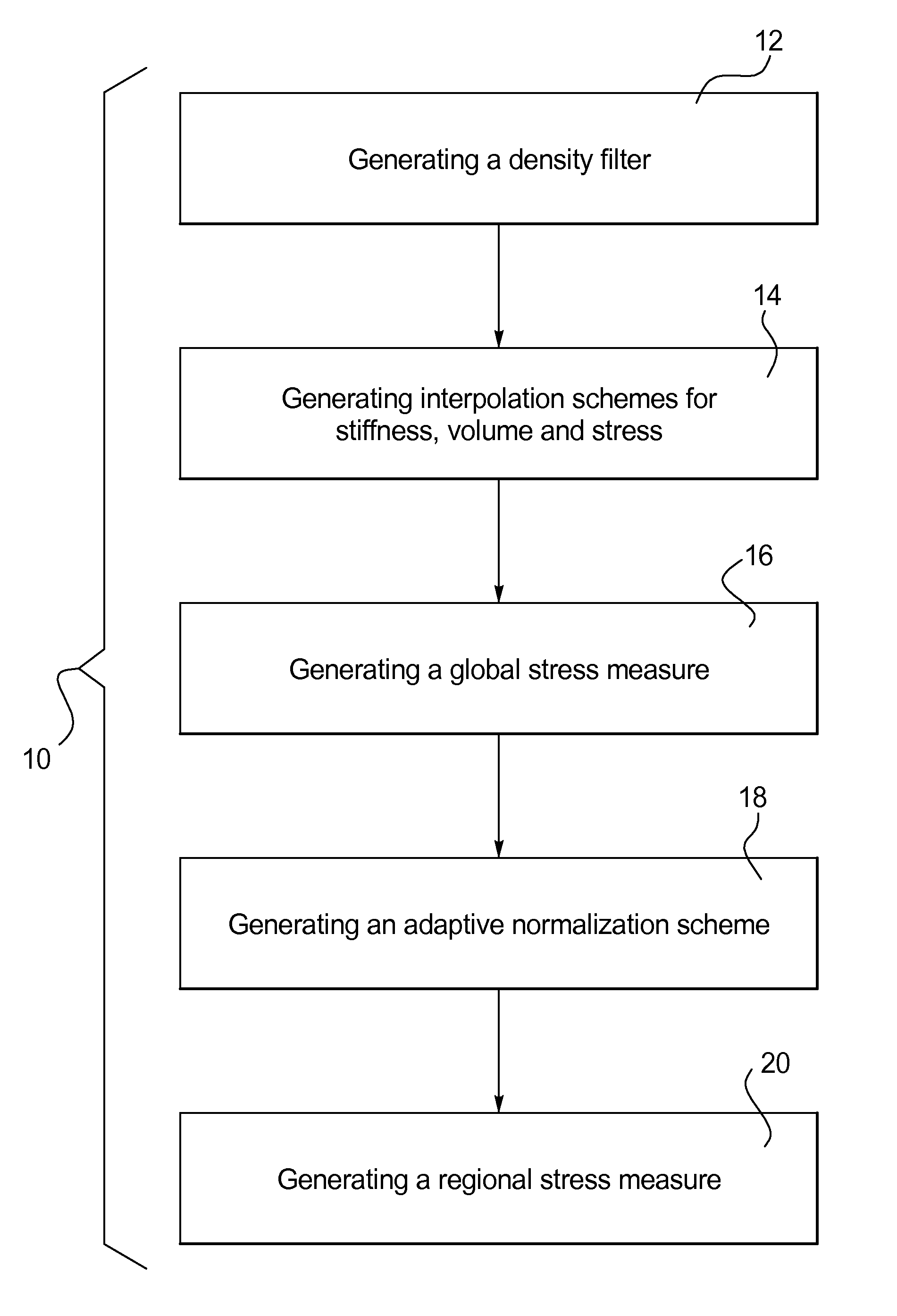
[0024]Referring to the drawings and with particular reference to FIG. 3, an exemplary method for performing stress-based topology optimization is provided and referred to as reference number 10. It is understood that the teachings of the disclosure may be used to construct stress-based topology optimization techniques above and beyond those specifically disclosed below. One of ordinary skill in the art will readily understand that the following are only exemplary embodiments.

[0025]Turning to FIG. 3, an exemplary method 10 for performing stress-based topology optimization is provided. The method 10 may include a step 12 of generating a density filter for length scale control, a step 14 of generating interpolation schemes for stiffness, volume and stress, a step 16 of generating a global stress measure, a step 18 of generating an adaptive normalization scheme to precisely control the local stress level and a step 20 of generating a regional stress measure.

[0026]The density filtering t...


PUM


Abstract

A method (10) for performing stress-based topology optimization of a structure (2, 102, 202) on a computational device (302) is provided. Upon receiving a problem definition of the structure (2, 102, 202) from an input device (304) coupled to an input of the computational device (302), the method (10) may generate a density filter, interpolation schemes for stiffness, volume and stress, a global stress measure, an adaptive normalization scheme and a regional stress measure, to determine an optimized stress-based solution to the problem defined. The method (10) may further enable the optimized solution to be rendered for display at an output device (306) coupled to an output of the computational device (302).

Description

CROSS-REFERENCE TO RELATED APPLICATION[0001]This is a non-provisional application claiming priority under 35 U.S.C. 119(e) to U.S. Provisional Patent Application Ser. No. 61 / 172,400 filed on Apr. 24, 2009.TECHNICAL FIELD[0002]This disclosure relates generally to systems and methods for performing stress-based topology optimization.BACKGROUND[0003]Topology optimization is well known in the art of structural design and is commonly used for optimizing the structural characteristics of a given material. More specifically, topology optimization employs a mathematical approach which aids design engineers in optimizing the distribution of a material for a given set of loads and boundary conditions so as to meet structural target performance requirements. There are several different techniques for conducting topology optimization. Among those, the material distribution technique has been well established and proven adequate in industries worldwide. However, the developments in the material ...

Claims


Application Information

Patent Timeline
IPC IPC(8): G06F17/50
CPCG06F17/5018G06F30/23
Inventor LE, CHAU H.NORATO, JULIAN A.BRUNS, TYLER E.HA, CHRISTOPHERTORTORELLI, DANIEL
Owner CATERPILLAR INC
Learn More