Configuring Animations and Events for Operator Interface Displays in a Process Control System

a control system and operator interface technology, applied in the field of process plants, can solve the problems of difficult or impossible for the configuration engineer to discern at once the configuration of all events, and achieve the effect of reducing or eliminating the opening and dismissing dialog, and facilitating the configuration of graphics and control strategies

Active Publication Date: 2010-10-28
FISHER-ROSEMOUNT SYST INC
View PDF18 Cites 44 Cited by
  • Summary
  • Abstract
  • Description
  • Claims
  • Application Information

AI Technical Summary

Benefits of technology

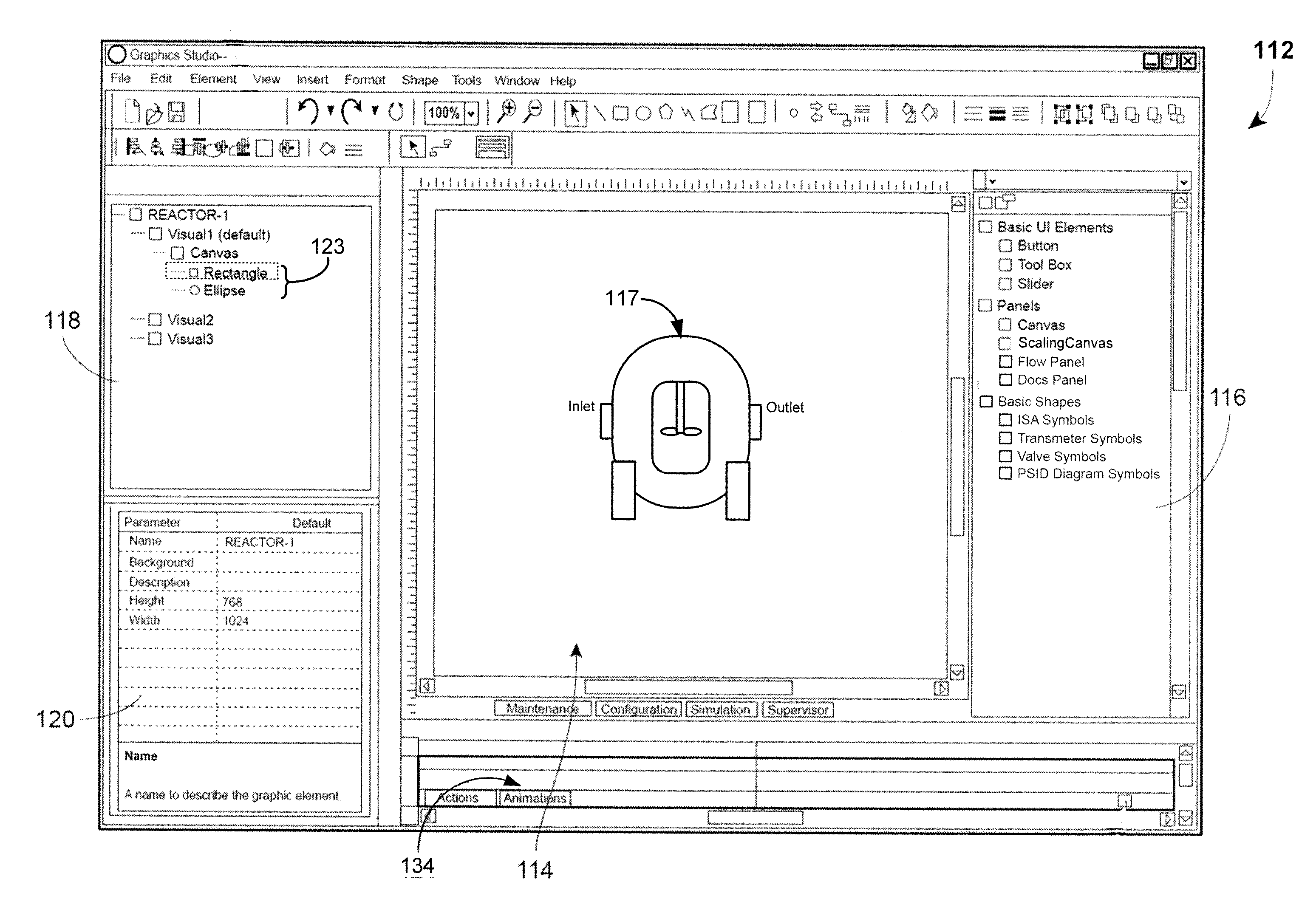
[0011]A graphic display editor or control strategy editor for creating operator displays, configuring control strategies, and other event and animation editing in a process control plant or system may present a coherent view for the multiple graphical or control strategy items depicted within or associated with the display and strategy. For each graphical item, an animation view may show, in a hierarchical manner, properties of the graphical item such as default and modified values, animation expressions, event handler scripts, and other viewable or modifiable characteristics of the graphical item and its sub-elements. The animation view may allow a configuration engineer to group, order, and filter various configurations of the graphical item properties within a single display to present a cohesive view of how the graphical items within the display have been or are capable of being configured for event handling and animation presentation within the operator display. Further, when configuring a control strategy within the process control plant, a control strategy view may allow the user to view quickly view and configure control strategies without opening an closing a dialog for each configuration task. Providing a cohesive, hierarchical view may facilitate graphics and control strategy configuration tasks by organizing and presenting the relevant graphics and control strategy information for the user to reduce or eliminate opening and dismissing dialogs for each task.
[0013]The editor as herein described may also configure an animation or event for a graphical representation of process control plant entity in a process control plant operator display by displaying, in a diagram view of an animation view editor, a selected graphical item that may include a visual representation of a physical or a logical entity within the process control plant and one or more sub-elements having one or more user-configurable properties for one or more of the animation or the event. The editor may further configure the graphical representation by displaying the one or more user-configurable properties of the selected graphical item in an animation pane of the editor and arranging the displayed user-configurable properties in the animation pane to facilitate completion of a configuration task.

Problems solved by technology

Because the dialog window may only be accessed for each event or animation individually, it may be difficult or impossible for the configuration engineer to discern at once the configuration of all events and animations associated with one or more graphic items depicted in the display, or the display configuration, generally.

Method used


Image

  • Configuring Animations and Events for Operator Interface Displays in a Process Control System
  • Configuring Animations and Events for Operator Interface Displays in a Process Control System
  • Configuring Animations and Events for Operator Interface Displays in a Process Control System

Examples


Embodiment Construction

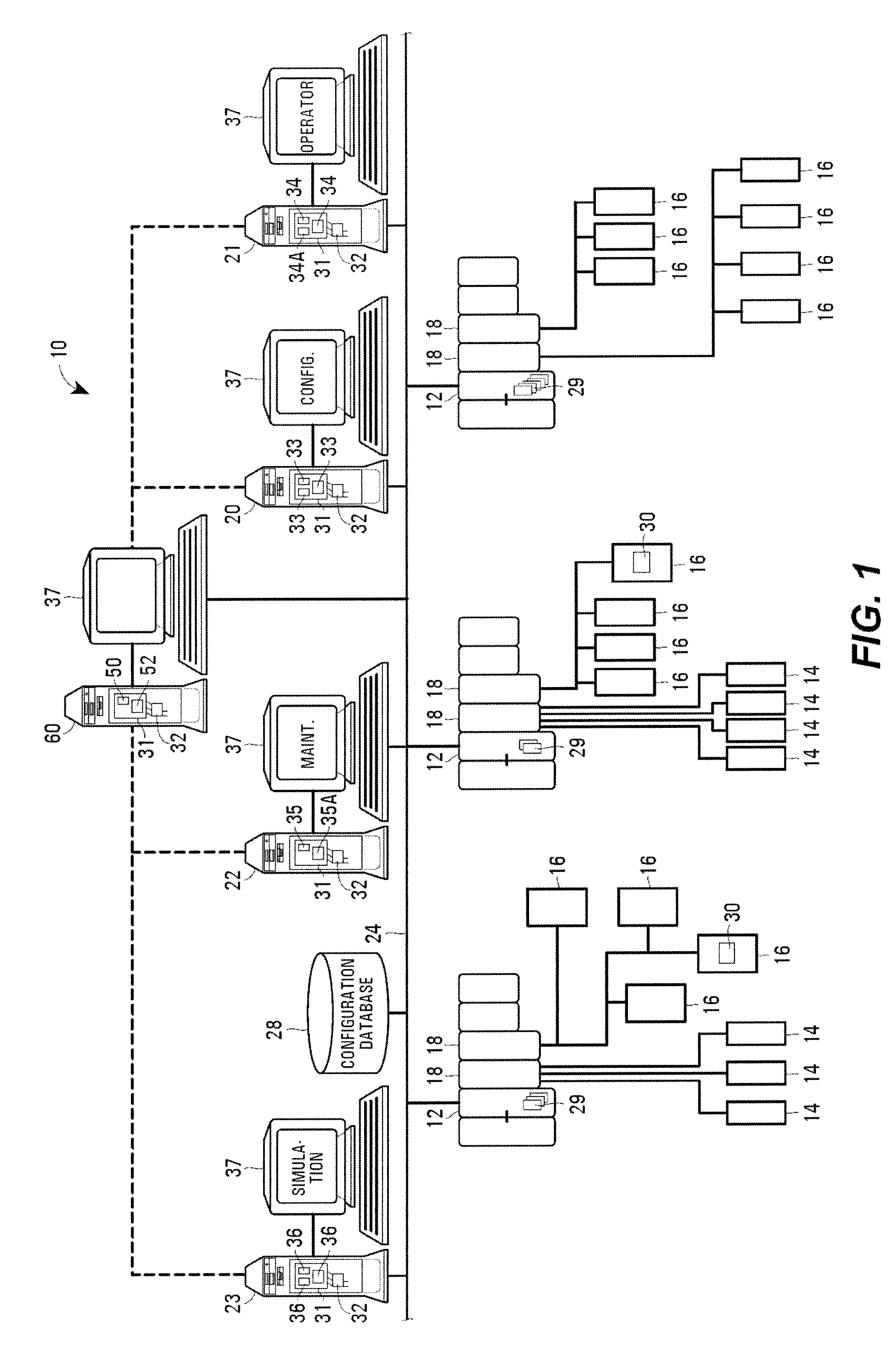
[0023]FIG. 1 illustrates an example process plant 10 in which system level graphical support is provided to various functional areas of the plant 10. As is typical, the process plant 10 includes a distributed process control system having one or more controllers 12, each connected to one or more field devices 14 and 16 via input / output (I / O) devices or cards 18 which may be, for example, Fieldbus interfaces, Profibus interfaces, HART interfaces, standard 4-20 ma interfaces, etc. The controllers 12 are also coupled to one or more host or operator workstations 20-23 via a data highway 24 which may be, for example, an Ethernet link. A database 28 may be connected to the data highway 24 and operates as a data historian to collect and store parameter, status and other data associated with the controllers and field devices within the plant 10 and / or as a configuration database that stores the current configuration of the process control system within the plant 10 as downloaded to and stor...


PUM


Abstract

A graphical editor for creating operator displays and configuring control strategies in a process control plant or system may present a coherent view for the multiple graphical or control strategy items depicted within or associated with the display and strategy. For each graphical item, the view may hierarchically show default and modified values, animation expressions, and event handler scripts. The view may allow a configuration engineer to group, order, and filter various graphical or control strategy items within a single display to present a cohesive view of how the multiple items within the display are capable of being configured for events, animations, and control strategies within the operator display. Providing this cohesive view may allow the user to view and configure graphical items and control strategies without having to open and dismiss dialogs for each configuration task.

Description

TECHNICAL FIELD [0001]The present invention relates generally to process plants and, more particularly, to configuring animations of components and various activities associated with plant configuration, control, maintenance, and simulation.DESCRIPTION OF THE RELATED ART [0002]Distributed process control systems, like those used in chemical, petroleum or other processes, typically include one or more process controllers communicatively coupled to one or more field devices via analog, digital or combined analog and digital buses. The field devices, which may be, for example, valves, valve positioners, switches and transmitters (e.g., temperature, pressure, level and flow rate sensors), are located within the process environment and perform process functions such as opening or closing valves, measuring process parameters, etc. Smart field devices, such as the field devices conforming to the well-known Fieldbus protocols, like the FOUNDATION™ Fieldbus protocol, may also perform control...

Claims


Application Information

Patent Timeline
Patent Type & Authority Applications(United States)
IPC IPC(8): G06F3/048
CPCG05B19/0426G05B19/409G05B2219/23424G05B2219/23291G05B2219/23261G06F9/451G05B19/41885
Inventor HAMMACK, STEPHEN G.CAMPNEY, BRUCE H.REYES, JOSE AMILCAR G.VALDERAMA, RYAN G.
Owner FISHER-ROSEMOUNT SYST INC
Why Eureka
Try Eureka