Apparatus for preheating batches of glass cullet

Inactive Publication Date: 2010-11-04
ARDAGH GLASS
View PDF4 Cites 0 Cited by
  • Summary
  • Abstract
  • Description
  • Claims
  • Application Information

AI Technical Summary

Benefits of technology

[0010]Proceeding from this, it is an object of the present invention to improve the preheater apparatus mentioned in the introduction to such an extent that the batch of glass cullet, after it has passed or flowed throug

Problems solved by technology

However, the discharge of the preheated batch of glass cullet from the preheater is problematic.
A disadvantage of this prior art s

Method used


Image

  • Apparatus for preheating batches of glass cullet
  • Apparatus for preheating batches of glass cullet

Examples


Embodiment Construction

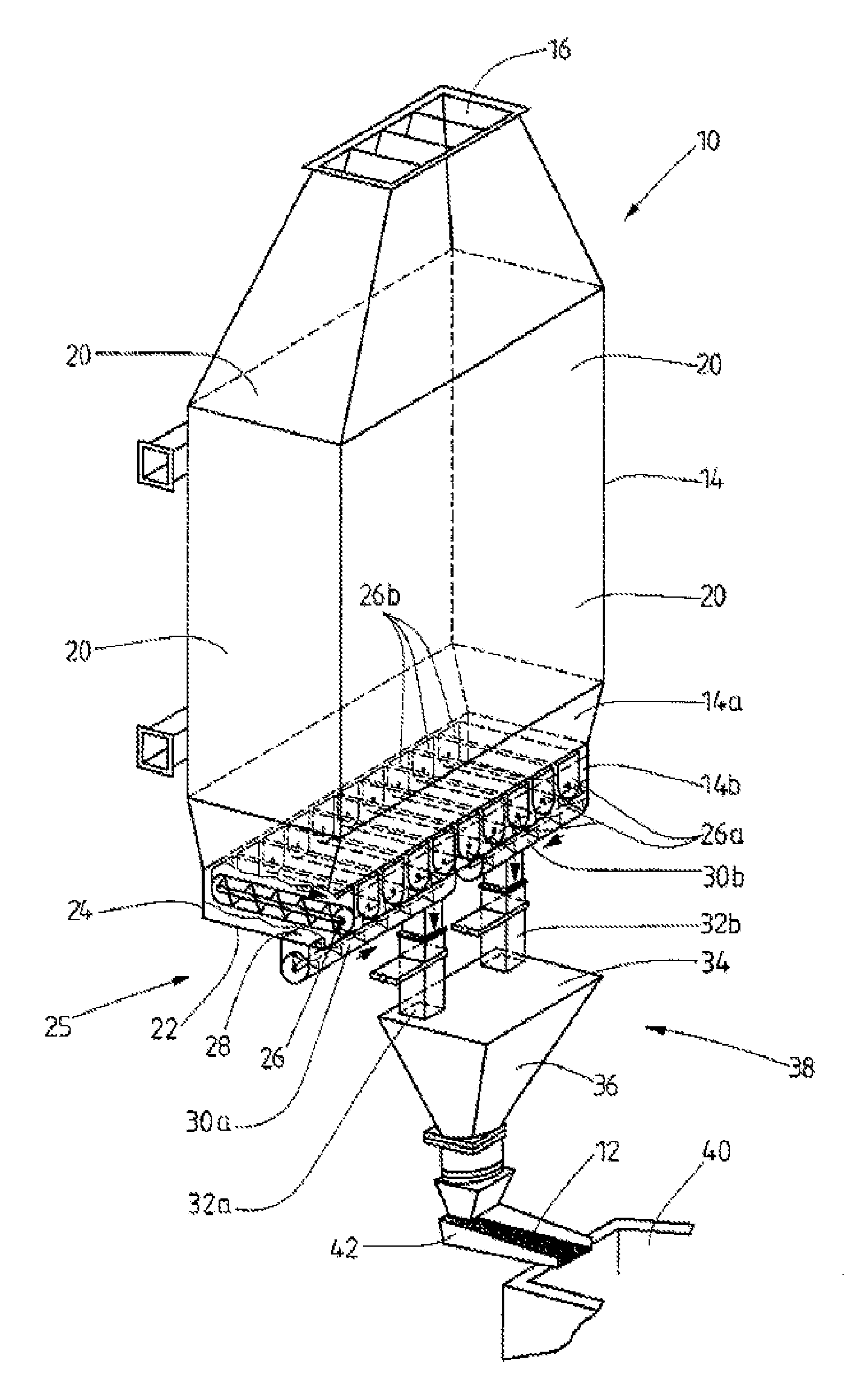
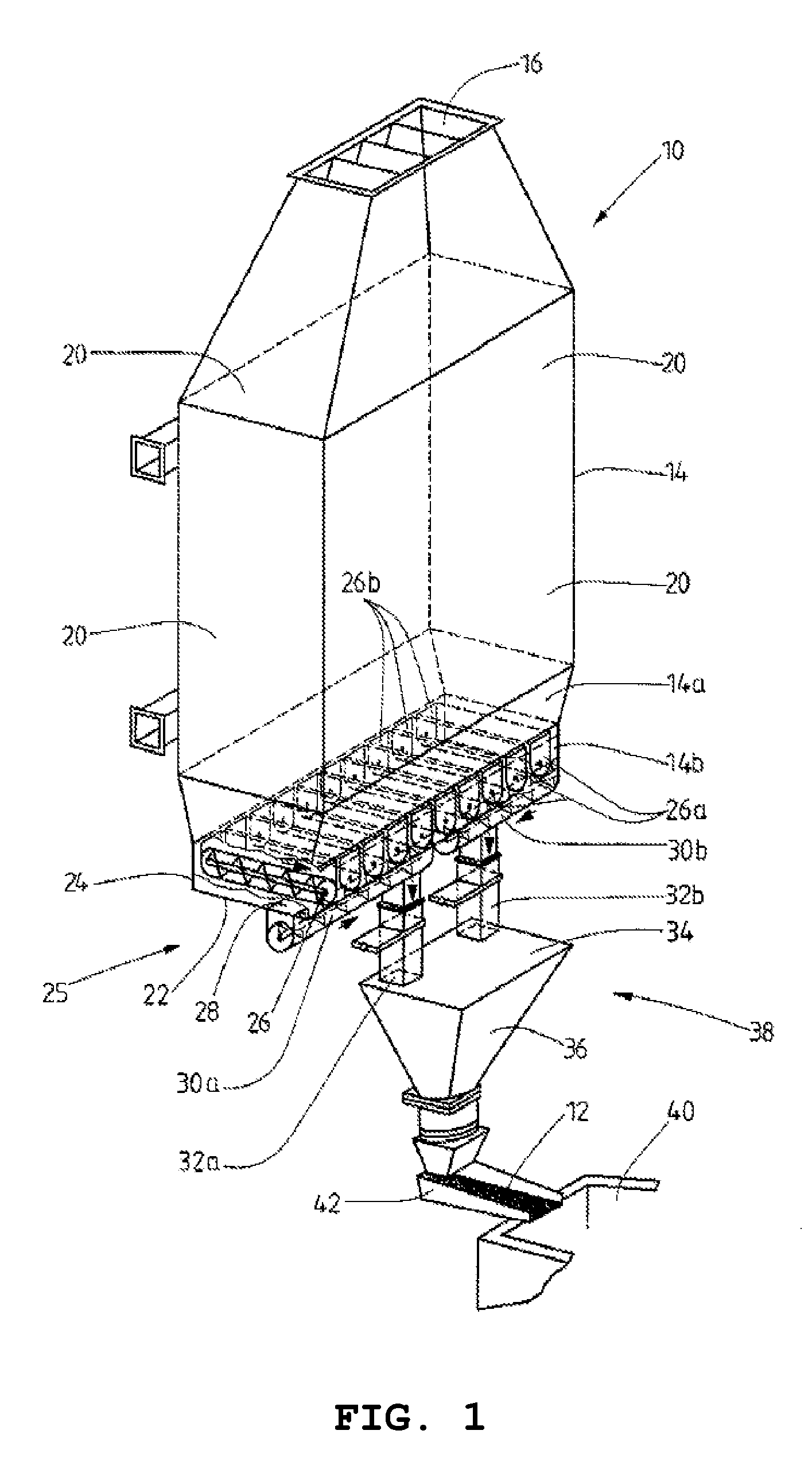
[0025]FIG. 1 shows an apparatus 10 according to the invention for preheating a batch 12 of glass cullet, comprising a bunker 14. The batch 12 of glass cullet to be preheated is fed to the bunker 14 through an upper opening 16, in a manner which is not shown. The measures required for the feeding operation are known in the prior art.

[0026]The batch 12 of glass cullet generally flows approximately continuously from top to bottom in the bunker 14, at least when the batch 12 of glass cullet is fed in continuously. In this case, the batch 12 of glass cullet is heated as it passes through the bunker 14. Hot offgases which have been produced during a melting operation in a glass melting furnace (not shown) are fed to the bunker 14 in order to preheat the batch 12 of glass cullet therein.

[0027]A large number of horizontally extending flow ducts (not shown for the sake of simplicity) are located within the main part of the bunker 14, which, in the present case, is rectangular and formed by u...


PUM

PropertyMeasurementUnit
Angleaaaaaaaaaa

Abstract

An apparatus for preheating a batch (12) of glass cullet which is preferably enriched with raw materials for glass production, comprising a bunker (14) preferably having flow ducts for the passage of warm (off)gas. To discharge the preheated batch of glass cullet from the bunker, the apparatus has one or more discharge worms (26), by way of which the batch of glass cullet can be conveyed to at least one outflow opening (28) in the base region of the bunker (14).

Description

STATEMENT OF RELATED APPLICATIONS[0001]This application is based on and claims the benefit of German Patent Application No. 10 2009 019 454.1 having a filing date of 4 May 2009, which is incorporated herein in its entirety by this referenceBACKGROUND OF THE INVENTION[0002]1. Technical Field[0003]The present invention relates to an apparatus for preheating a batch of glass cullet which is preferably enriched with raw materials for glass production, comprising a bunker preferably having flow ducts for the passage of warm (off)gas.[0004]2. Prior Art[0005]An apparatus of this type is known, for example, from German Patent No. DE 34 16 317 C2. During the glass production process, this apparatus serves to utilize the thermal energy of the offgases produced during the combustion of the raw materials in the melting furnace for preheating the batch of glass cullet. For this purpose, the offgases are generally guided along flow ducts through the bunker, specifically through the batch of glass...

Claims


Application Information

Patent Timeline
IPC IPC(8): C03B5/26
CPCC03B3/023Y02P40/50
Inventor BARKLAGE, HANSJURGENCIELEBACK, WOLFGANGSCHAPER, ROLF
Owner ARDAGH GLASS
Why Eureka
Try Eureka