Method for forming a film of lithium metal or lithium alloys and an apparatus for the same

Inactive Publication Date: 2007-03-01
FUCHITA NANOTECH +1
View PDF1 Cites 3 Cited by
  • Summary
  • Abstract
  • Description
  • Claims
  • Application Information

AI Technical Summary

Benefits of technology

[0015] However, ultra fine particles are not used for forming a film in the gas phase deposition method of the above JP2002-100346A reference, although they are used in the JP8-209330A reference. The film forming principles are different between the above

Problems solved by technology

Further the purity of the film of lithium is low in the method of the JP2002-100346 publication.
Thus, discharge

Method used


Image

  • Method for forming a film of lithium metal or lithium alloys and an apparatus for the same
  • Method for forming a film of lithium metal or lithium alloys and an apparatus for the same
  • Method for forming a film of lithium metal or lithium alloys and an apparatus for the same

Examples


first embodiment

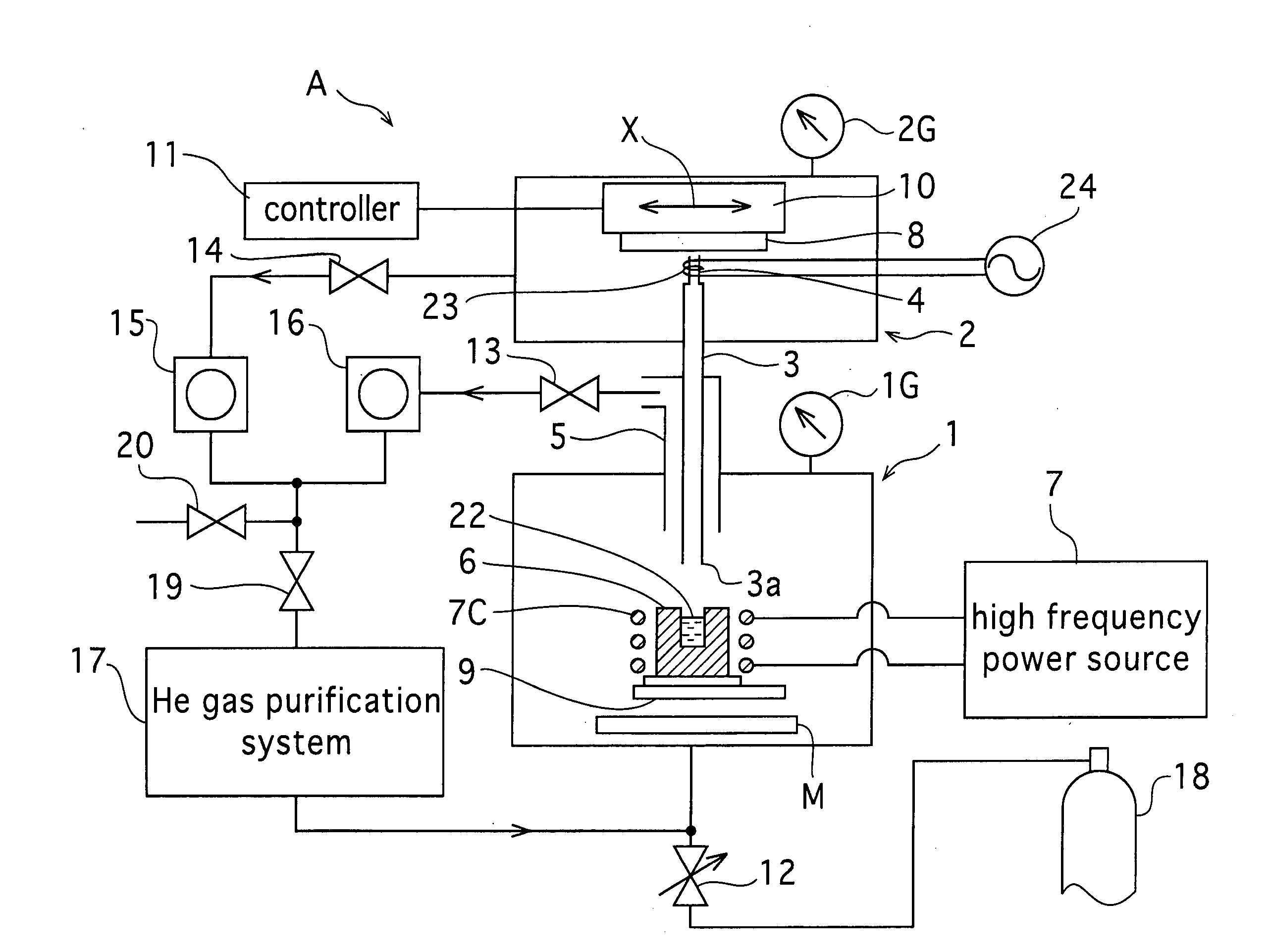
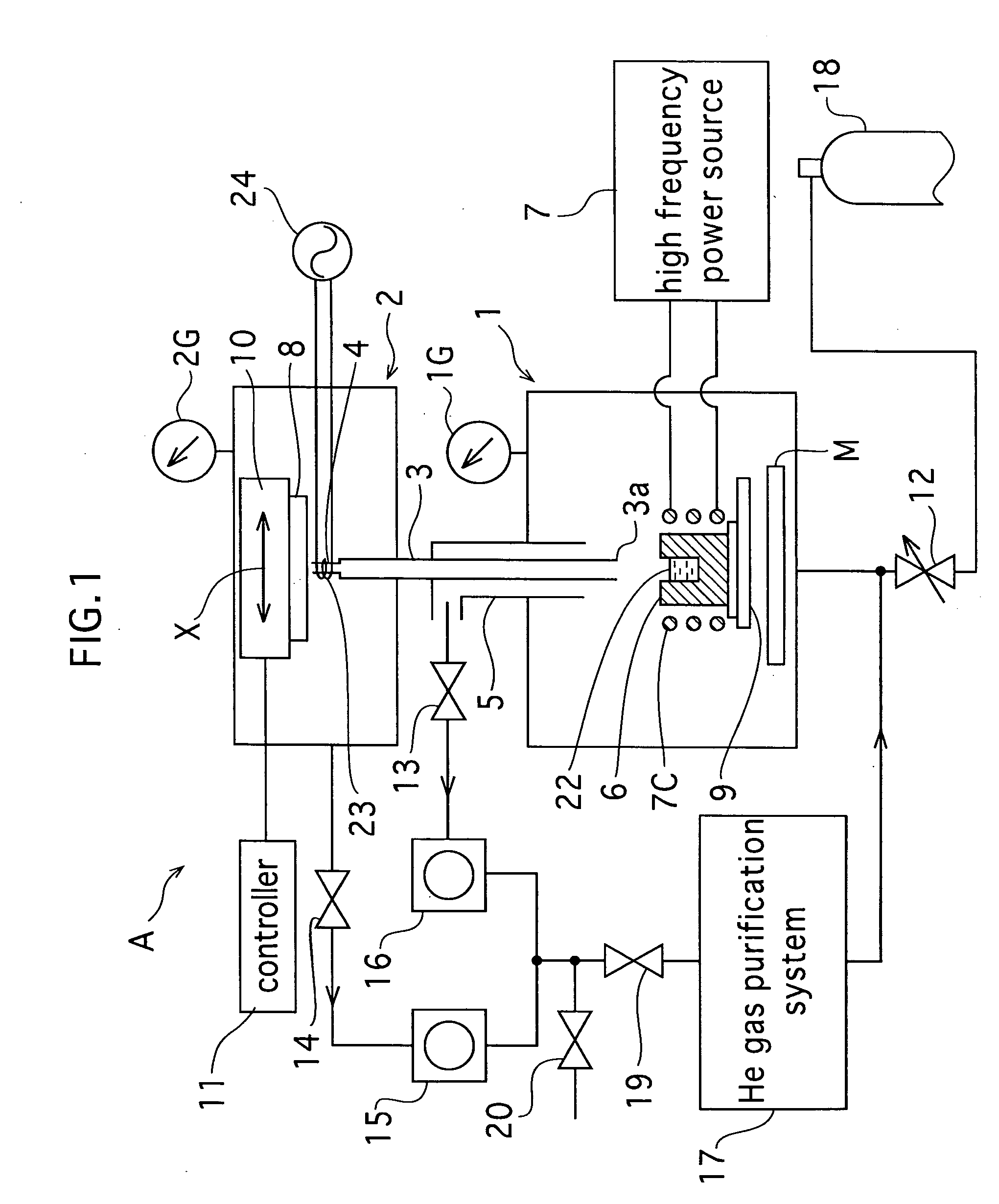
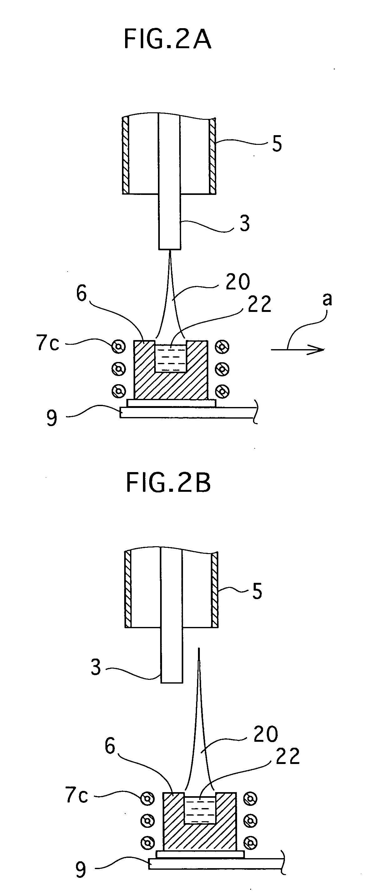
[0037]FIG. 1 shows a gas deposition apparatus A of the first embodiment. Generally, it consists of an ultra fine particle evaporation chamber 1, a transfer pipe 3, and a film forming chamber 2, which are arranged in a vertical direction. A crucible 6 which is made of, for example, tantalum, the inner diameter and the outer diameter of which are equal to 38mm(p and 40 mmφ. respectively, is arranged in the ultra fine particle evaporation chamber 1. The height of the crucible 6 is equal to 40 mm. Evaporation material 22 (Li) is contained in the crucible 6. An electromagnetic coil 7C for heating inductively lithium 22 is wound around the crucible 6. The coil 7C is connected to a radio (high) frequency (150 kHz) electric power source 7 which is arranged outside of the ultra fine particle evaporation chamber 1.

[0038] A helium (He) gas is introduced into the ultra fine particle evaporation chamber 1 through a mesh-filter type introducing port M, so that the ultra fine particle evaporation...

second embodiment

[0063]FIG. 3 shows a gas deposition apparatus B of the second embodiment. The parts which correspond to those in FIG. 1, are denoted by the same, but primed, reference numerals. Generally, it consists of an ultra fine particle evaporation chamber 1′, a transfer pipe 3′, and a film forming chamber 2′, which are arranged in a vertical direction. A crucible 6′, the inner diameter of which is equal to 5.0 mm, is arranged in the ultra fine particle evaporation chamber 1′. Evaporation material 22′ (Li) is contained in the crucible 6′. An electromagnetic coil 7C′ for inductively heating lithium in the crucible 6′ is wound around the crucible 6′. The coil 7C′ is connected to a radio (high) frequency electric power source 7′ which is arranged outside of the ultra fine particle evaporation chamber 1′.

[0064] A helium (He) gas is introduced into the ultra fine particle evaporation chamber 1′ through a mesh-filter type introducing port M′, so that the ultra fine particle evaporation chamber 1′ ...


PUM

PropertyMeasurementUnit
Temperatureaaaaaaaaaa
Pressureaaaaaaaaaa
Fractionaaaaaaaaaa

Abstract

A lithium or lithium alloy film forming method comprises: the step of heating and evaporating lithium or lithium alloy under an atmosphere of inert gas in an ultra fine particle producing chamber to produce ultra fine particles of lithium or lithium alloy therein; the step of transporting the ultra fine particles through a transfer pipe with the inert gas into a film forming chamber under vacuum atmosphere; the step of jetting the ultra fine particles onto a substrate arranged in the film forming chamber from a nozzle; the step of moving a substrate holder holding the substrate in the X-direction and/or Y-direction; the step of preheating the substrate at a predetermined temperature within the range of 100 to the melting point of lithium or lithium alloy: and the step of forming a film of lithium or lithium alloy on the substrate being moved with the substrate holder.

Description

BACKGROUND OF THE INVENTION [0001] 1. Field of the Invention [0002] This invention relates to a method for forming a film of lithium metal or lithium alloy and an apparatus for the same. [0003] 2. Description of the Prior Art [0004] Publication J8-209330A discloses a pattern forming method for a conductive metal thick film in which a conductive metal material is heated and evaporated with high frequency induction heat under an inert gas atmosphere, in an ultra fine particle evaporation chamber, and produced ultra fine particles are transported in a pipe, with the inert gas, into a film forming chamber in a vacuum. The fine particles are jetted onto a substrate, arranged in the film forming chamber, from a nozzle heated at a temperature under the melting point of the ultra fine particles, with the applied pressure of the inert gas. The nozzle or the substrate is moved at an arbitrary speed and the thick film of conductive metal is formed with a desired thickness in a desired pattern....

Claims


Application Information

Patent Timeline
IPC IPC(8): B22F3/24C22C33/02
CPCB22F7/08B22F9/12B22F2998/00C22B26/12C23C14/14C23C14/22C23C14/564C23C14/228B22F2201/20
Inventor FUCHITA, EIJIHONJO, YOSHIYUKIYAMAKAWA, YUKIO
Owner FUCHITA NANOTECH
Why Eureka
Try Eureka