
Fluid transfer device

a technology of fluid transfer device and liquid transfer device, which is applied in the direction of packaging foodstuffs, instruments, packaged goods, etc., can solve the problems of wasting fluid, difficult for such a person to ensure the fluid is stable, and difficult to provide the required drug stability in the devi

Active Publication Date: 2010-11-04
MANNKIND CORP
View PDF44 Cites 92 Cited by
  • Summary
  • Abstract
  • Description
  • Claims
  • Application Information

AI Technical Summary

Benefits of technology

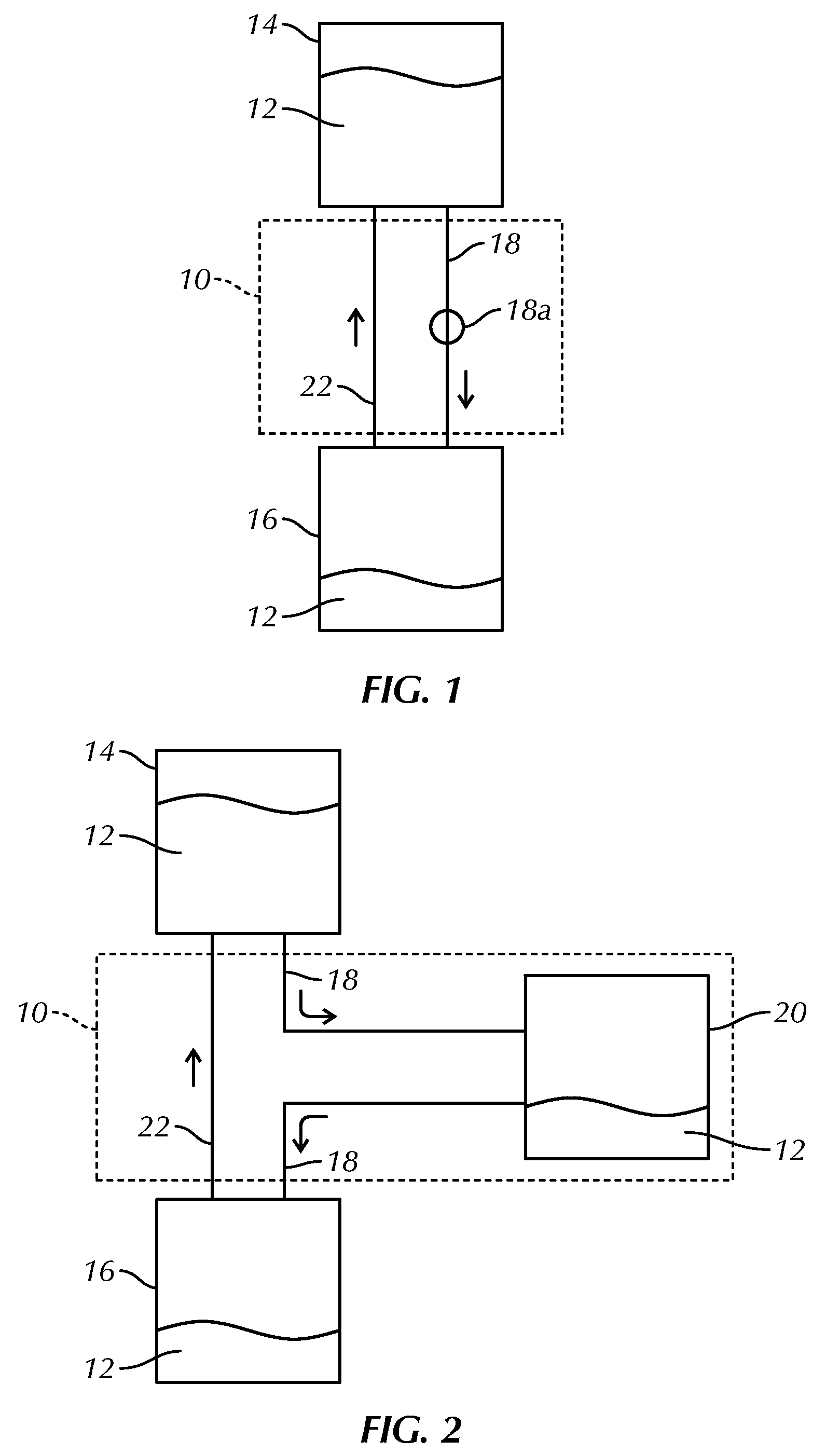
[0013]In another embodiment, a fluid transfer device comprises a metering reservoir, a first one-way channel fluidly connected with the metering reservoir, and a second one-way channel fluidly connected with the metering reservoir. In one embodiment, the first channel includes a first cannula and the second channel includes a second cannula. In one embodiment, the first cannula includes a first beveled tip. In one embodiment, the first cannula is configured to overcome the surface tension resistance of a fluid within a supply reservoir positioned below the first beveled tip. In one embodiment, the second cannula includes a second beveled tip. In a further embodiment, the fluid transfer device comprises a member supporting the first and second cannulas, the first cannula extending in a first direction from the member and the second cannula extending in a second direction from the member, the first direction being generally opposite the second direction. In one embodiment, the metering reservoir extends from the member generally in the first direction. In a further embodiment, the fluid transfer device comprises a manifold that supports the first and second cannulas, the manifold forming at least part of the first channel and at least part of the second channel.
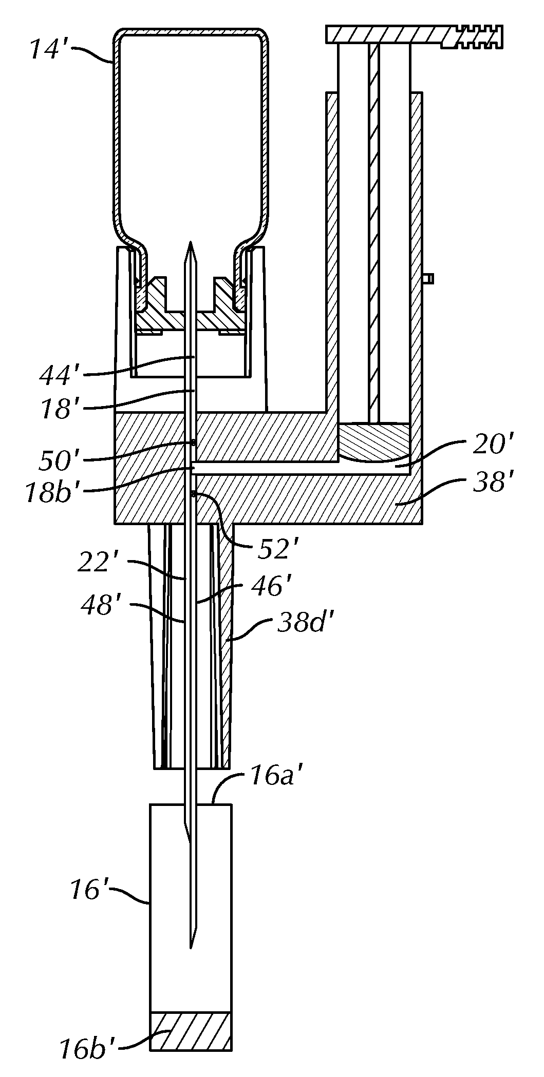
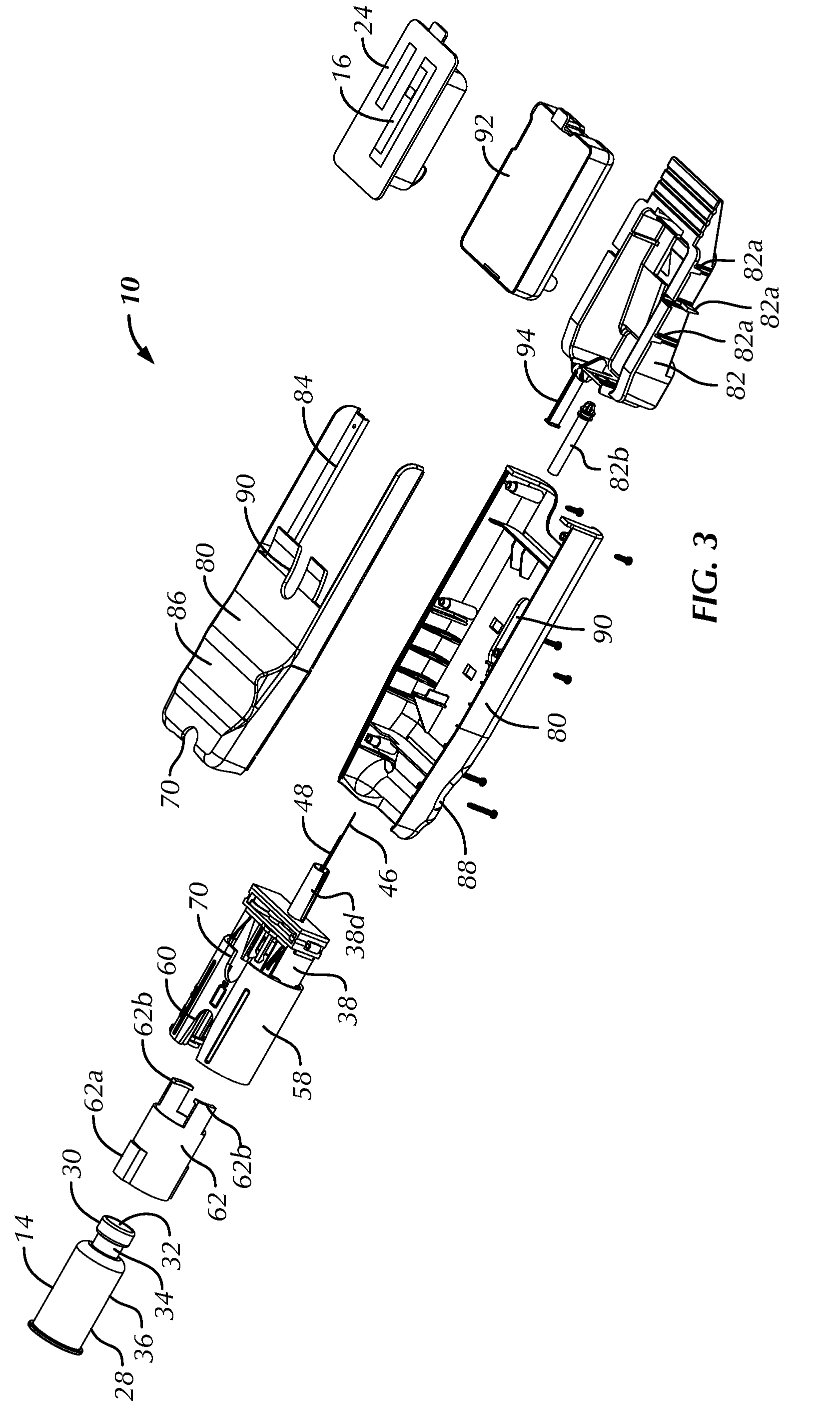
[0014]In a further embodiment, the fluid transfer device comprises a member supporting the first and second channels, and a tray support connected to the member and configured to align a fill reservoir with the second channel. In a further embodiment, the fluid transfer device comprises a tray slideably connected to the tray support and configured to accommodate the fill reservoir. In one embodiment, at least one of the tray support and the tray further comprises a safety lock configured to prevent the tray from moving relative to the tray body when the tray is empty and exposing the second channel. In a further embodiment, the fluid transfer device comprises a safety reservoir configured to removeably couple with the tray and comprising a penetrable body configured to block access to the second channel in an initial position. In a further embodiment, the fluid transfer device comprises a third channel having a first end proximate a distal end of the first channel and a second end proximate a distal end of the second channel. In one embodiment, the distal end of the first channel and the first end of the third channel are configured to sealingly engage with a supply reservoir and the distal end of the second channel and the second end of the third channel are each configured to sealingly engage with a fill reservoir. In one embodiment, the third channel is partially within the first channel. In one embodiment, the third channel is at least partially generally coaxial with the first channel. In one embodiment, the first end of the third channel is curved toward an inner side wall of the first channel proximate the distal end of the first channel. In one embodiment, the first channel includes a first cannula, the second channel includes a second cannula and the third channel includes a third cannula. In one embodiment, the second end of the third cannula comprises a beveled tip. In one embodiment, the second and third cannula extend away from the metering reservoir, the second cannula extends further from the metering reservoir than the third cannula channel. In one embodiment, the metering reservoir has a volume that is greater than a volume of a fill reservoir configured to be fluidly engaged with the second one-way channel. In one embodiment, the fill reservoir comprises a fluid transfer delivery device.
[0015]In a further embodiment, the fluid delivery device comprises at least one first catch proximate the first channel and configured to releasably retain a supply reservoir. In a further embodiment, the fluid delivery device further comprises at least one second catch proximate the first channel, the at least one second catch spaced from the first channel further than the at least one first catch is spaced from the first channel. In one embodiment, the metering reservoir includes a plunger. In one embodiment, the plunger comprises a plunger rod and a plunger tip. In a further embodiment, the fluid delivery device comprises a supply support configured to accommodate a supply reservoir proximate the first channel. In one embodiment, the metering reservoir has an adjustable metering stop. In one embodiment, the first and second channels comprise less than 100 μl of fluid transfer space. In one embodiment, the first and second channels comprise less than 20 μl of fluid transfer space. In a further embodiment, the fluid delivery device comprises an upper support coupled to the first one-way channel, and a lower support coupled to the second one-way channel, the lower support being moveable with respect to upper support, wherein moving the lower support relative to the upper support changes the volume of the metering reservoir.

Problems solved by technology

If filled by the manufacturer, it may be difficult to provide the required drug stability in the device since the fluid may be stored from several weeks to a number of years and the fluid delivery device manufacturer must then be responsible for providing the required fluid.
If filled by someone downstream, it is difficult for such a person to ensure that the fluid has completely filled the reservoir, i.e. that the reservoir and fluid path do not contain any undesirable air bubbles.
Also, transferring fluid from one container to another typically results in at least some wasted fluid.

Method used


Image

  • Fluid transfer device
  • Fluid transfer device
  • Fluid transfer device

Examples


Embodiment Construction

[0044]Referring to the drawings in detail, wherein like reference numerals indicate like elements throughout, there is shown in FIGS. 1-23 a fluid transfer device, generally designated 10, in accordance with an exemplary embodiment of the present invention.

[0045]Referring to FIGS. 1, 2, and 3, in one embodiment, the fluid transfer device 10 forms part of a system that generally permits a fluid 12 from a supply reservoir 14 to be transferred to a fill reservoir 16. The supply reservoir 14 and the fill reservoir 16 may be any suitable containers for holding fluids. In one embodiment, the fluid transfer device 10 sealingly transfers fluid between two otherwise sealed containers having predetermined volumes. In one embodiment, the supply reservoir 14 is a drug vial 28. In one embodiment, the fill reservoir 16 is contained within an ambulatory fluid delivery device 24. In one embodiment, the fill reservoir 16 is a cartridge that is initially in a refracted position (i.e. filled with air)...


PUM

PropertyMeasurementUnit
volumeaaaaaaaaaa
volumeaaaaaaaaaa
volumeaaaaaaaaaa

Abstract

A fluid transfer device for transferring fluid between a supply reservoir and a fill reservoir includes a metering reservoir and a manifold that forms at least part of a first channel that is fluidly connected with the metering reservoir. The first channel comprises a first cannula extending from the manifold. The manifold forms at least part of a second channel fluidly connected with the metering reservoir. The second channel comprises a second cannula extending from the manifold. A third channel extends through the manifold and comprises a third cannula having a first end proximate a distal end of the first cannula and a second end proximate a distal end of the second cannula. A first check valve is disposed within the first channel and a second check valve is disposed within the second channel.

Description

CROSS-REFERENCE TO RELATED APPLICATIONS[0001]This application claims the benefit of U.S. Provisional Patent Application No. 61 / 175,329 filed May 4, 2009 entitled “Fluid Transfer Device and Method of Use” which is incorporated by reference herein in its entirety.BACKGROUND OF THE INVENTION[0002]The present invention generally relates to a fluid transfer device and, in at least one embodiment, relates to a fluid transfer device for transferring fluid from a sealed container such as a vial to a sealed fluid delivery device such as an ambulatory drug delivery device.[0003]A wide range of injectable drug delivery devices are known in which a fluid medicament, such as insulin, is stored in an expandable-contractible reservoir. In such devices, the fluid is delivered to the patient from the reservoir by forcing the reservoir to contract. The term “injectable” is meant to encompass subcutaneous, intradermal, intravenous and intramuscular delivery.[0004]Such devices can be filled by the manu...

Claims


Application Information

Patent Timeline
Patent Type & Authority Applications(United States)
IPC IPC(8): B65B3/04
CPCA61J1/2089A61J2001/2017A61J2001/2037A61J2001/2058B65B3/26G01F11/262A61J1/2096A61J2001/2072A61J1/201A61J1/2017A61J1/2037A61J1/2058A61J1/2072Y10T137/8593
Inventor GONNELLI, ROBERT R.LEVESQUE, STEVEN F.STANDLEY, ROBERT L.
Owner MANNKIND CORP
Features
  • Generate Ideas
  • Intellectual Property
  • Life Sciences
  • Materials
  • Tech Scout
  • Unparalleled Data Quality
  • Higher Quality Content
  • 60% Fewer Hallucinations
Learn More