
Magnetic rotational hardstop for robot

a robot and magnetic rotation technology, applied in the direction of interengaging clutches, mechanical control devices, instruments, etc., can solve the problems of limiting the range of the robot within the environment, breaking or entanglement of cables, and standard cables through the shoulder also cannot be used

Active Publication Date: 2010-11-04
NOVELLUS SYSTEMS
View PDF30 Cites 34 Cited by
  • Summary
  • Abstract
  • Description
  • Claims
  • Application Information

AI Technical Summary

Benefits of technology

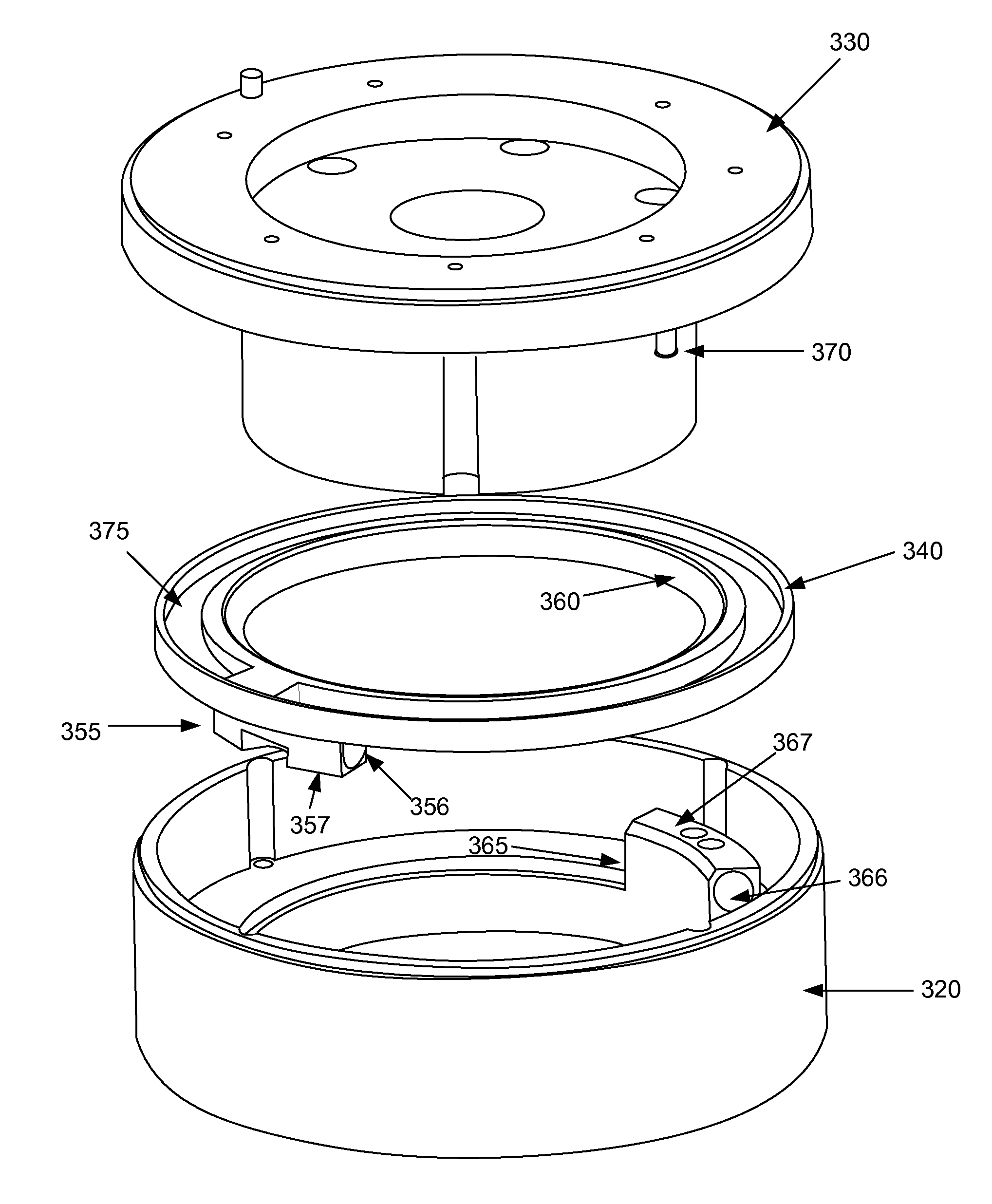
[0003]Rotational hardstop assemblies that provide greater than 360 degrees of non-continuous rotation for rotating mechanisms are provided. In certain embodiments, an assembly is used to provide between 360 and 720 degrees of rotation for the shoulder axis of a robot, such as a wafer transfer robot. The rotational hardstop assemblies include opposing magnets. According to various embodiments, the opposing magnets provide non-contact engagement and produce no contact noise nor have any wear over time. The rotational hardstop assemblies provide the ability to access locations from either direction of rotation of a robot cylindrical coordinate system.
[0010]In certain embodiments, the one or more magnets of the stationary and rotational magnet assemblies are arced such that the curvature of the magnet(s) of the stationary magnetic assembly matches that of the magnet(s) of the rotatable magnetic assembly. This allows the full possible opposing force between the magnets to be used for engagement.
[0011]In certain embodiments, engagement between the stationary member and the rotatable stop member is non-contact engagement. Engagement occurs when a pole of the rotatable magnetic assembly is rotated into a proximal position to a pole of the stationary magnetic assembly. The opposing magnetic force (between two south poles or between two north poles) is enough to overcome the bearing or other force that allows the rotatable stop member to rotate with the rotating mechanism.

Problems solved by technology

Standard cables through the shoulder also cannot be used, as rotating over 360° will lead to breakage and or entanglement of the cables.
This also limits a robot's accessible range within an environment.

Method used


Image

  • Magnetic rotational hardstop for robot
  • Magnetic rotational hardstop for robot
  • Magnetic rotational hardstop for robot

Examples


Embodiment Construction

[0025]In the following detailed description of the present invention, numerous specific embodiments are set forth in order to provide a thorough understanding of the invention. However, as will be apparent to those skilled in the art, the present invention may be practiced without these specific details or by using alternate elements or processes. In other instances well-known processes, procedures and components have not been described in detail so as not to unnecessarily obscure aspects of the present invention.

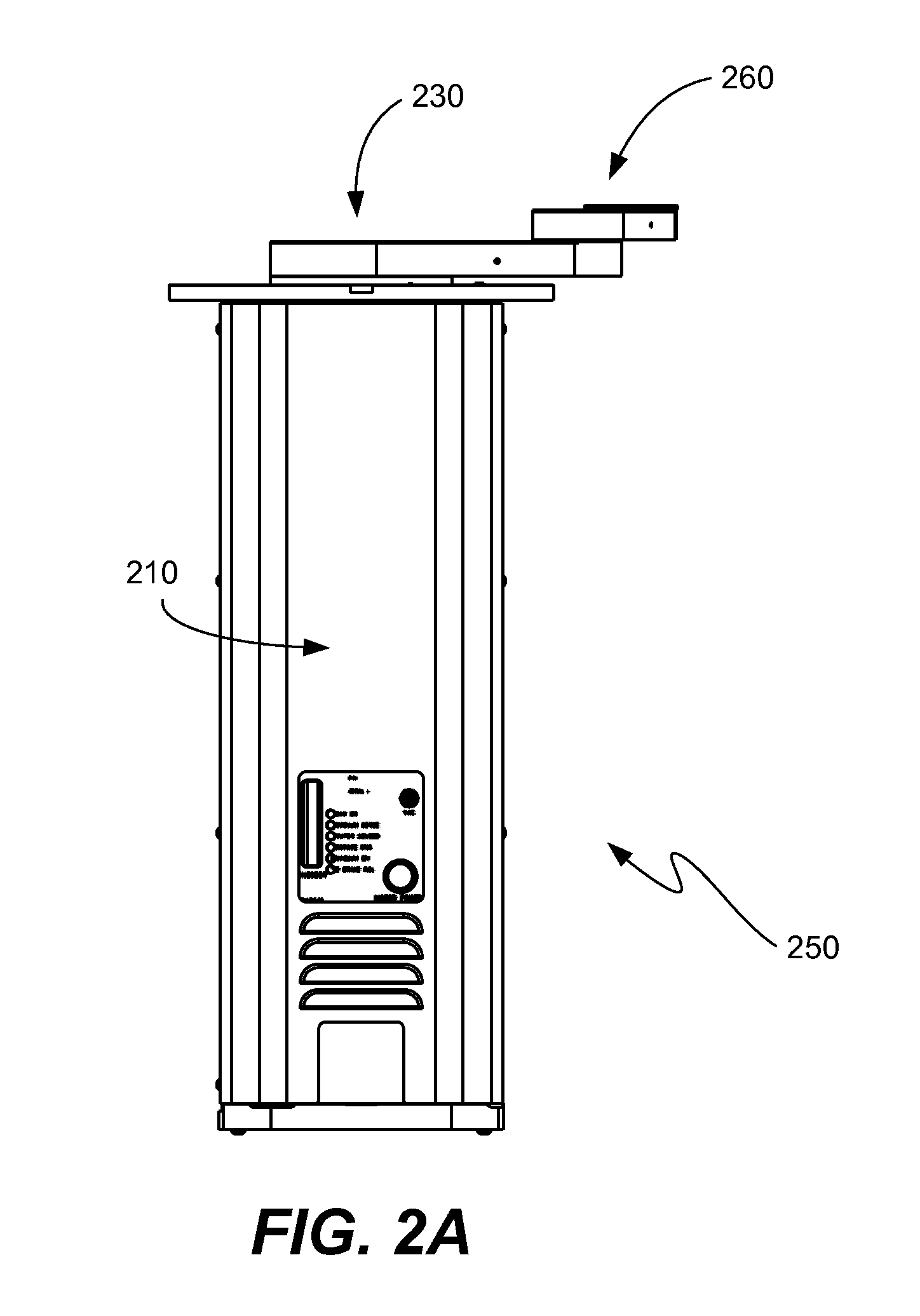
[0026]The apparatuses and methods described herein may be used to provide greater than 360° of rotation of a rotatable member or mechanism about a Z-axis. For the purposes of discussion, the below description refers to the mechanism being a rotatable robot arm. However, one of skill in the art will understand that the rotational magnetic hardstop assemblies described are not so limited, but may be used to provide greater than 360° non-continuous rotation greater of any rota...


PUM


Abstract

Rotational hardstop assemblies that provide greater than 360 degrees of non-continuous rotation for rotating mechanisms are provided. In certain embodiments, an assembly is used to provide 630 or more degrees of rotation for the shoulder axis of a robot, such as a wafer transfer robot. The rotational hardstop assemblies include opposing magnets as springs. According to various embodiments, the opposing magnets provide non-contact engagement and produce no contact noise nor have any wear over time. The rotational hardstop assemblies provide the ability to location from either direction of rotation of a robot cylindrical coordinate system.

Description

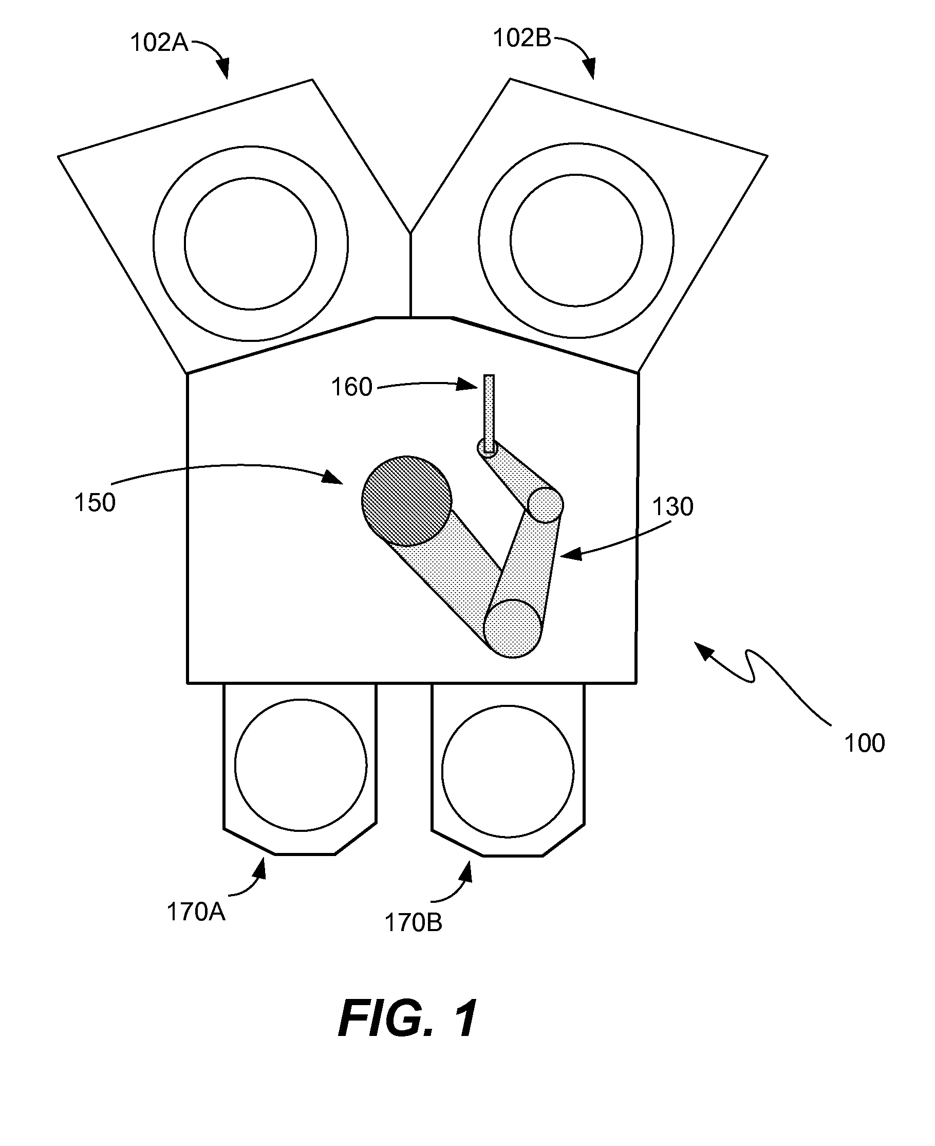
BACKGROUND OF THE INVENTION[0001]Cylindrical robots are used for picking and placing objects in a variety of applications including in wafer transfer systems in semiconductor processing. Their axes form a cylindrical coordinate system with the robot arms having radial, rotational and vertical motion. Robots that have greater than 360° rotation improve throughput by allowing objects to be picked and placed using a minimum or reduced number of moves than required with robots that have a range of motion of 360° or less.[0002]Continuous rotation functions well for optimized robot motion and throughput but requires an electrical and pneumatic slip ring assembly. Standard cables through the shoulder also cannot be used, as rotating over 360° will lead to breakage and or entanglement of the cables. Hardstop assemblies are used to prevent over-rotation of the arm, so that cables and tubings through the shoulder are not over-rotated past their functional limit. To prevent rotation over 360°,...

Claims


Application Information

Patent Timeline
IPC IPC(8): H01L21/68B25J18/00F16D71/00
CPCY10T74/20305H01L21/67742B25J9/101B25J15/06B25J15/0608
Inventor BLANK, RICHROBERTS, JIMTANG, WAYNEBERGESON, MICHAEL
Owner NOVELLUS SYSTEMS
Learn More