Reduced Density Glass Bubble Polymer Composite

a polymer composite and glass bubble technology, applied in dentistry, flooring, ceilings, etc., can solve the problems of inability to display composite properties, use of inorganic, non metallic or mineral particles in a polymer composite,

Active Publication Date: 2010-11-04
TUNDRA COMPOSITES LLC
View PDF102 Cites 49 Cited by
  • Summary
  • Abstract
  • Description
  • Claims
  • Application Information

AI Technical Summary

Problems solved by technology

A filled polymer, with the additive as filler, cannot display composite properties.
Many of these materials containing polymer and particulate are admixtures and are not true composites.
While a substantial amount of work has been done regarding composite materials generally, the use of inorganic, non metallic or mineral particles in a polymer composite has not been obtained.

Method used


Image

  • Reduced Density Glass Bubble Polymer Composite
  • Reduced Density Glass Bubble Polymer Composite
  • Reduced Density Glass Bubble Polymer Composite

Examples


example 1

Hollow Glass Spheres

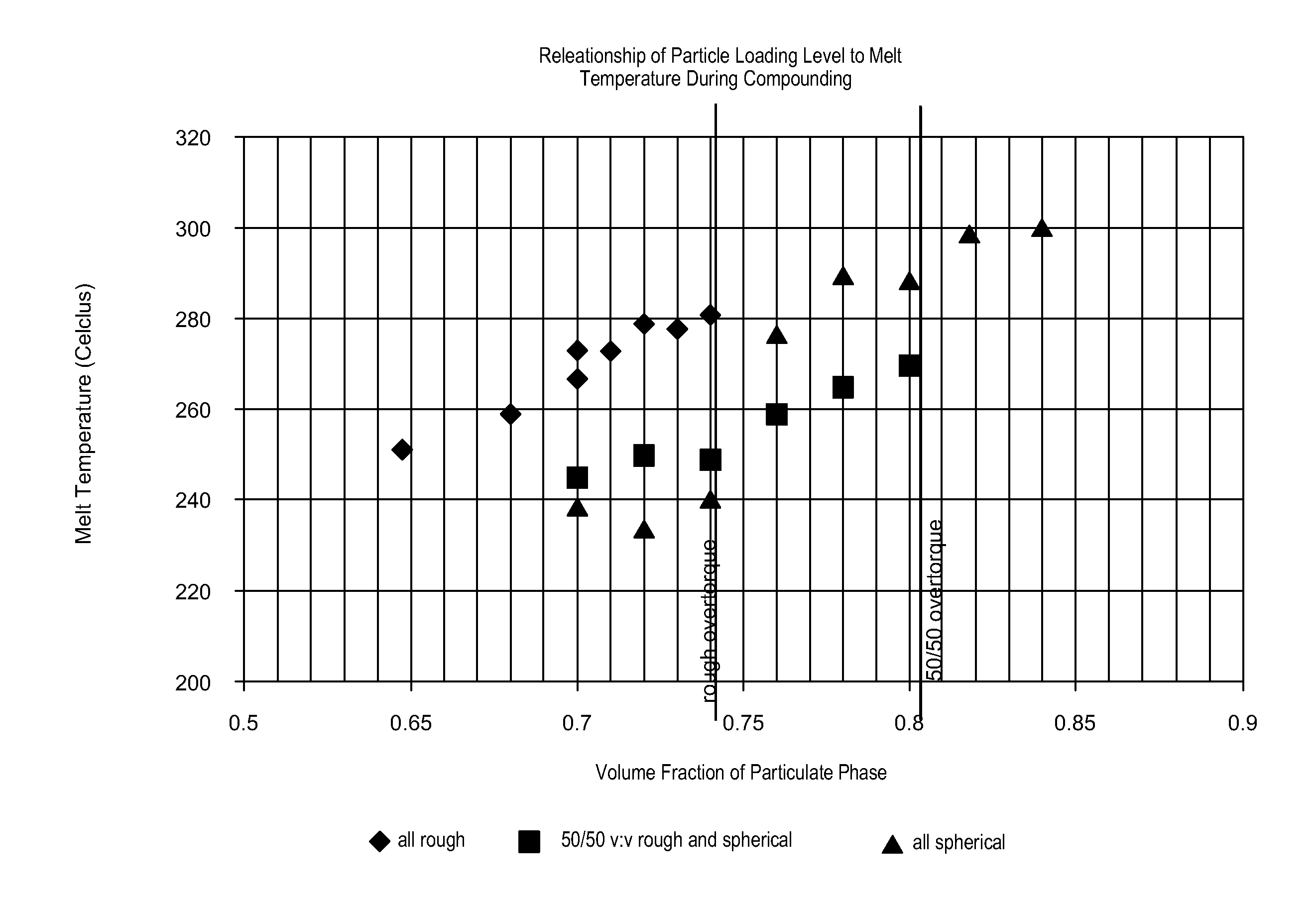
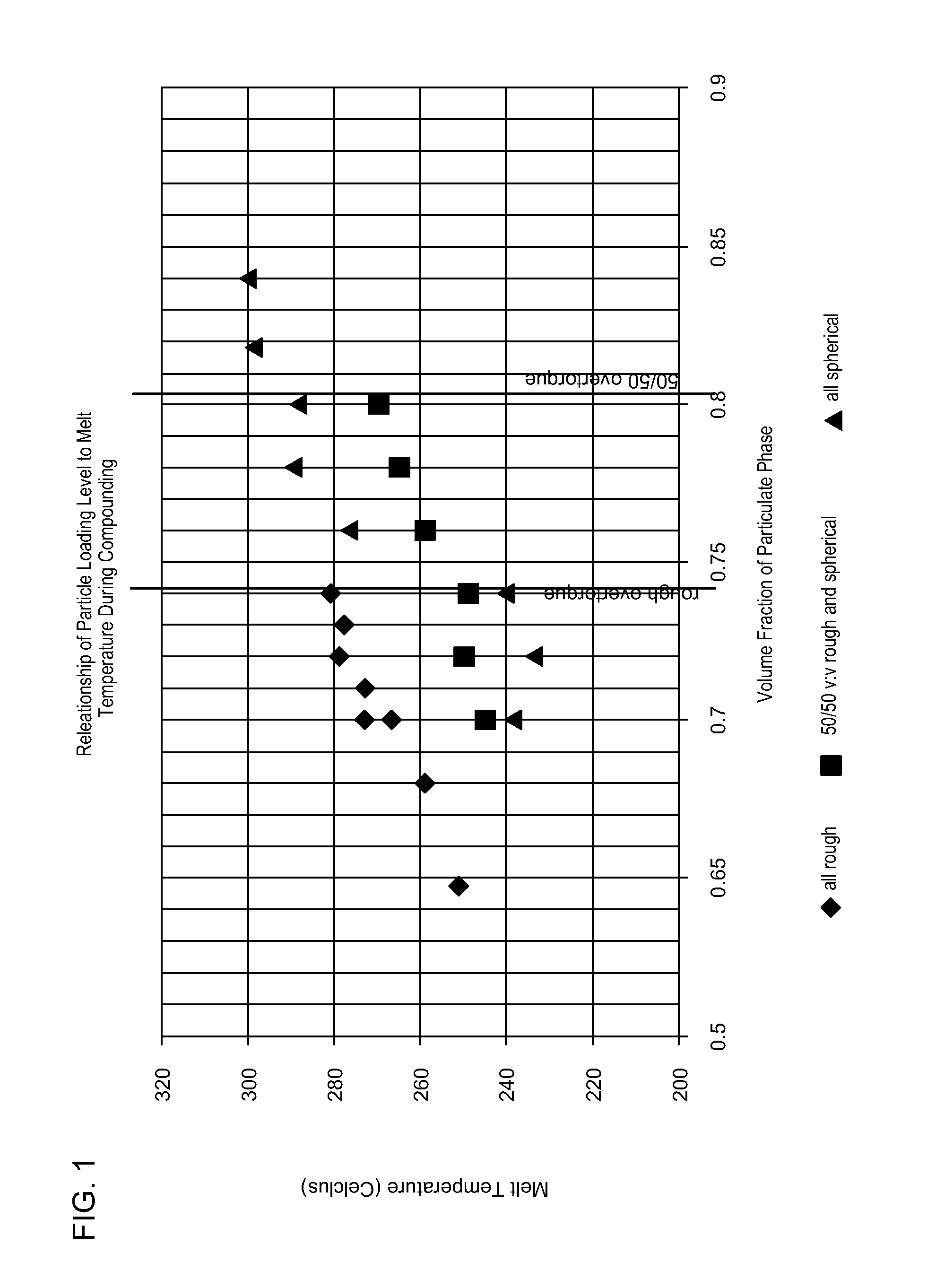
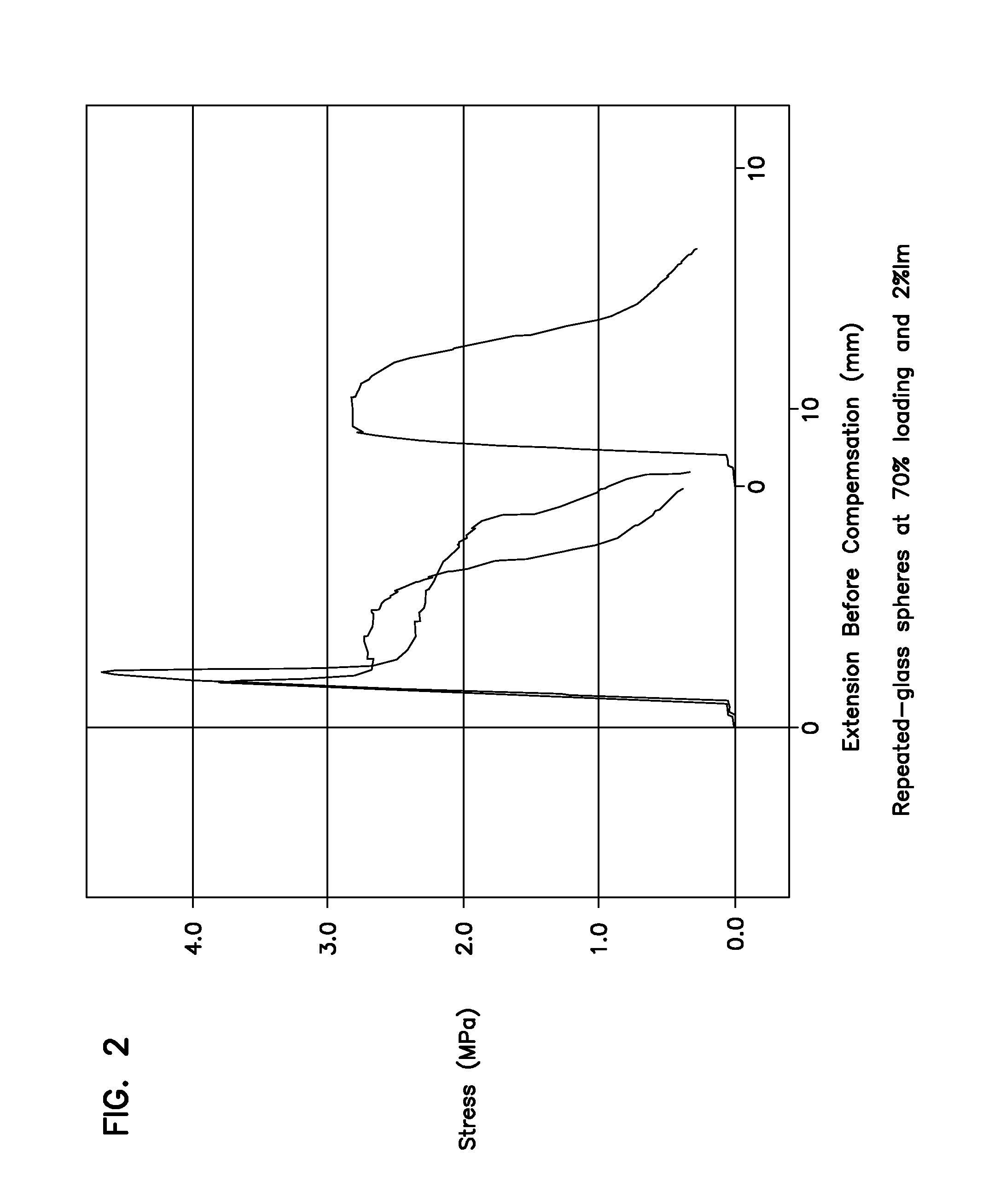
[0117]A supply of iM30k hollow glass bubbles were obtained from 3M Corporation (St. Paul, Minn.). The bubbles possess a density of approximately 0.6 g / cc. The bubbles were interfacailly modified with KR238S (KenRich Chemicals) with 4.8 parts of interfacial modifier to 100 parts particulate. The polymer phase was THV220 from Dyneon (St. Paul, Minn.). The bubbles were compounded into the polymer phase to a loading of 60 volume % hollow glass bubbles in the polymer phase. Samples were then extruded and ASTM tensile dogbones specimens made and tensile tested. Additionally, puck samples were made via the metallurgical press to confirm the formulations were near the targeted values.

[0118]Obvious differences were apparent during compounding. The product without modifier was brown / tan in color exiting the die plate, indicating degradation of the material. Additionally, the bubbles did not feed well and bridged at the infeed throat of the machine. As a result, the volumet...


PUM

PropertyMeasurementUnit
particle sizeaaaaaaaaaa
tensile elongationaaaaaaaaaa

Abstract

The invention relates to a hollow glass microsphere and polymer composite having enhanced viscoelastic and rheological properties.

Description

CROSS-REFERENCE TO RELATED APPLICATION[0001]This application claims the benefit of U.S. Provisional Patent Application Ser. No. 61 / 173,791, filed Apr. 29, 2009, which application is hereby incorporated by reference in its entirety.FIELD OF THE INVENTION[0002]The invention relates to a composite of a hollow glass microsphere and a polymer with modifiable properties to produce enhanced products. The novel properties are produced in the composite by novel interactions of the components. The hollow glass microsphere and polymer composite materials are a unique combination of a hollow glass microsphere typically particulate components and a polymer material that optimizes the composite structure and characteristics through blending the combined polymer and hollow glass micros to 90% of the base polymer materials to achieve true composite properties.BACKGROUND OF THE INVENTION[0003]Substantial attention has been paid to the creation of composite materials with unique properties. Included ...

Claims


Application Information

Patent Timeline
Patent Type & Authority Applications(United States)
IPC IPC(8): C08K7/28B32B3/26E04B1/82A61K6/884
CPCB60C1/00C08K3/22C08K7/28C08K9/00C08L21/00C08K9/04Y10T428/249974C08J5/04C08J2327/16C08J2327/18C08J2327/20C08K2003/2227C08K2201/005
Inventor HEIKKILA, KURT E.WILLIAMS, RODNEY K.KROLL, JOHN S.
Owner TUNDRA COMPOSITES LLC
Why Eureka
Try Eureka