Prevention of a rear crash during an automatic braking intervention by a vehicle safety system

a technology of automatic braking and rear crash prevention, which is applied in the direction of braking systems, instruments, analogue processes for specific applications, etc., can solve problems such as rear crash, and achieve the effect of reducing the danger of rear crash

a technology of automatic braking and rear crash prevention, which is applied in the direction of braking systems, instruments, analogue processes for specific applications, etc., can solve problems such as rear crash, and achieve the effect of reducing the danger of rear crash

US20100280726A1Inactive Publication Date: 2010-11-04ROBERT BOSCH GMBH

Image

  • Prevention of a rear crash during an automatic braking intervention by a vehicle safety system
  • Prevention of a rear crash during an automatic braking intervention by a vehicle safety system
  • Prevention of a rear crash during an automatic braking intervention by a vehicle safety system

Examples


Embodiment Construction

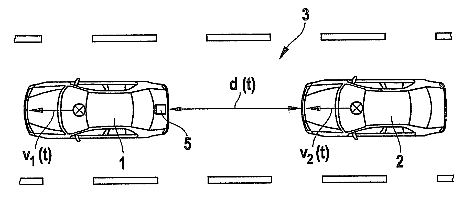
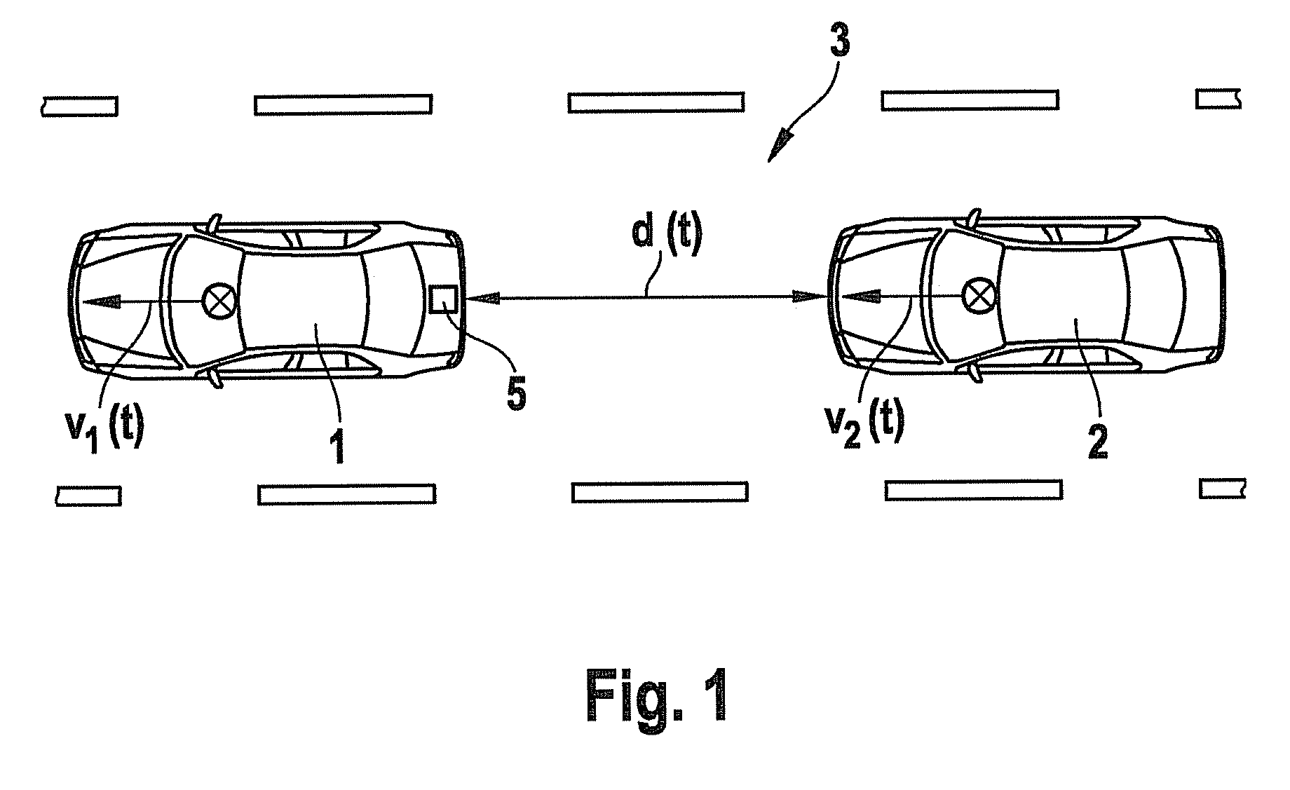
[0017]FIG. 1 shows two vehicles 1, 2 that are moving on a roadway 3 with a speed v1(t) or v2(t) respectively. The distance between the two vehicles is designated d(t).

[0018]At least front vehicle 1 has a vehicle safety system 5 that is capable of introducing an automatic emergency braking in certain driving situations, e.g. when there is the threat of a frontal collision, or after an initial collision. The overall system, including the sensors and the control device, is here represented schematically as block 5.

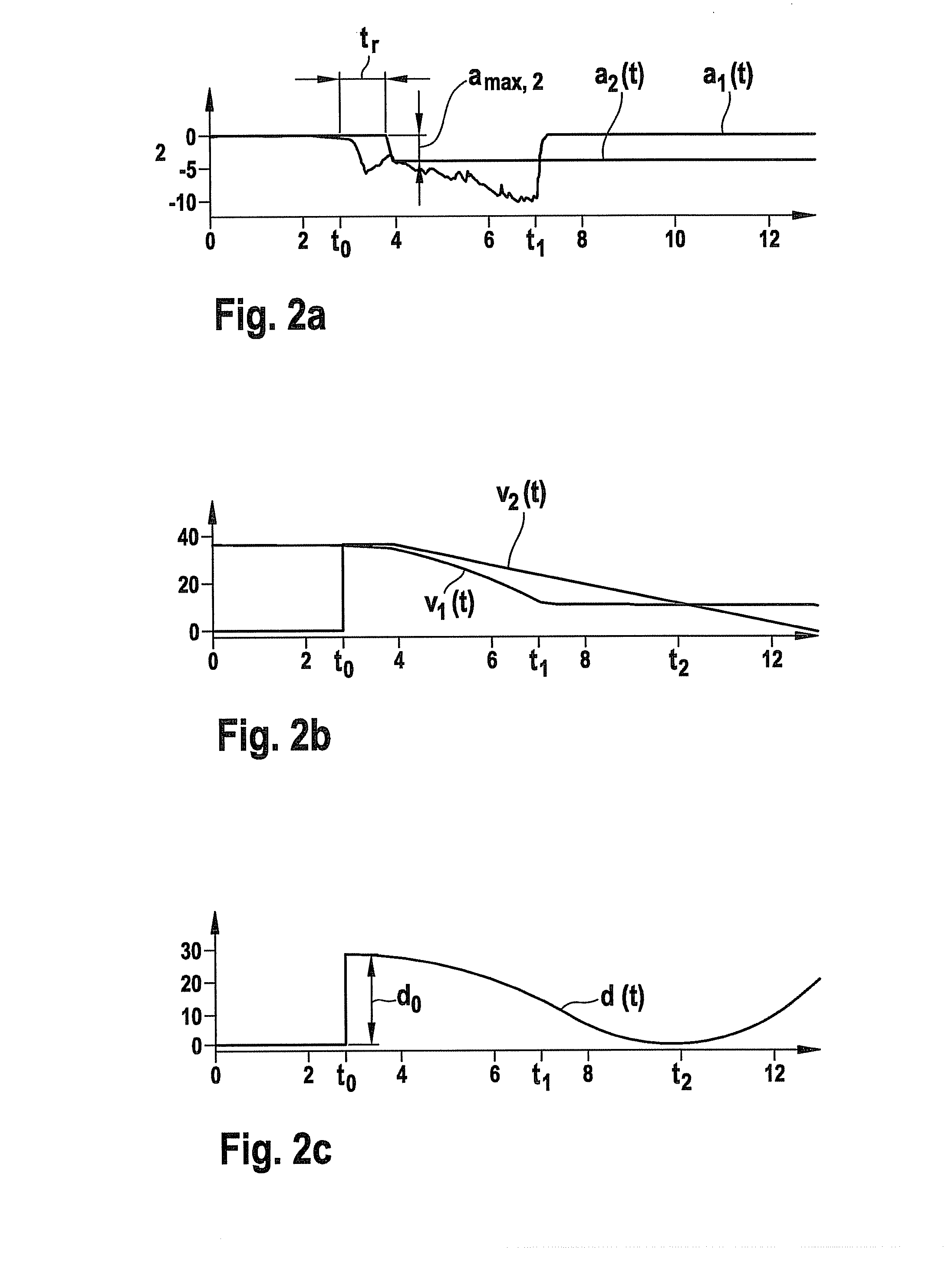
[0019]Upon recognition of a critical situation, an automatic braking is activated, and the vehicle brakes are at first actuated with a high braking force. Beginning from a particular point in time, the brakes are then at least partially released in order to reduce the danger or severity of a threatening rear crash. The point in time at which the brakes are released is calculated using a theoretical model for the approach of a hypothetical vehicle following behind, based on as...


PUM


Abstract

A method for preventing a rear crash after the activation of an automatic braking intervention by a vehicle safety system. The danger and severity of a possible rear crash by a vehicle following behind can be significantly reduced if a model is used for the approach of a hypothetical vehicle following behind, and on this basis a condition is determined for the release of the brake, and the brake is at least partially released when this condition occurs.

Description

FIELD OF THE INVENTION[0001]The present invention relates to a method for preventing a rear crash after activation of an automatic braking intervention by a vehicle safety system, as well as to a control device having a braking algorithm.BACKGROUND INFORMATION[0002]From the prior art, various vehicle safety systems are known that, in critical driving situations in which the vehicle is for example approaching an obstacle, introduce an automatic emergency braking (ANB). Such collision prevention systems standardly include a “look-ahead” sensor system that monitors the area in front of the vehicle and that automatically activates the driving brake when there is a threat of a frontal collision with another object. Depending on the driving situation, a full braking may also be carried out here. In addition, safety systems are also known that, after an initial collision, introduce an automatic emergency braking in order to reduce the severity of possible subsequent collisions. In interven...

Claims


Application Information

Patent Timeline
04 Nov 2010
Publication
US20100280726A1
IPC
B60T8/17; B60W10/18
CPC
B60T7/22; B60W2050/0031; B60W10/184
Inventors
STABREY, STEPHAN