
Multi-Phase Fluid Measurement Apparatus and Method

a fluid measurement and multi-phase technology, applied in the direction of instruments, borehole/well accessories, surveys, etc., can solve the problems of increasing the slip between gas and liquid, difficult to predict the flow rate of each component, and affecting the accuracy of the measurement results

Active Publication Date: 2010-11-04
AGAR CORP
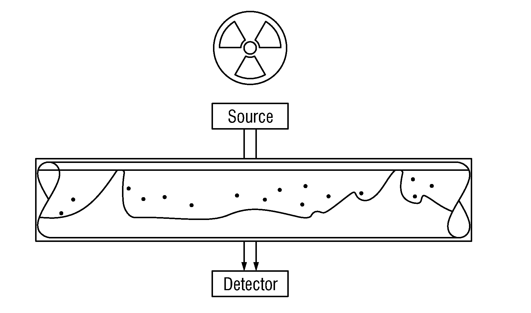
View PDF21 Cites 23 Cited by
  • Summary
  • Abstract
  • Description
  • Claims
  • Application Information

AI Technical Summary

Problems solved by technology

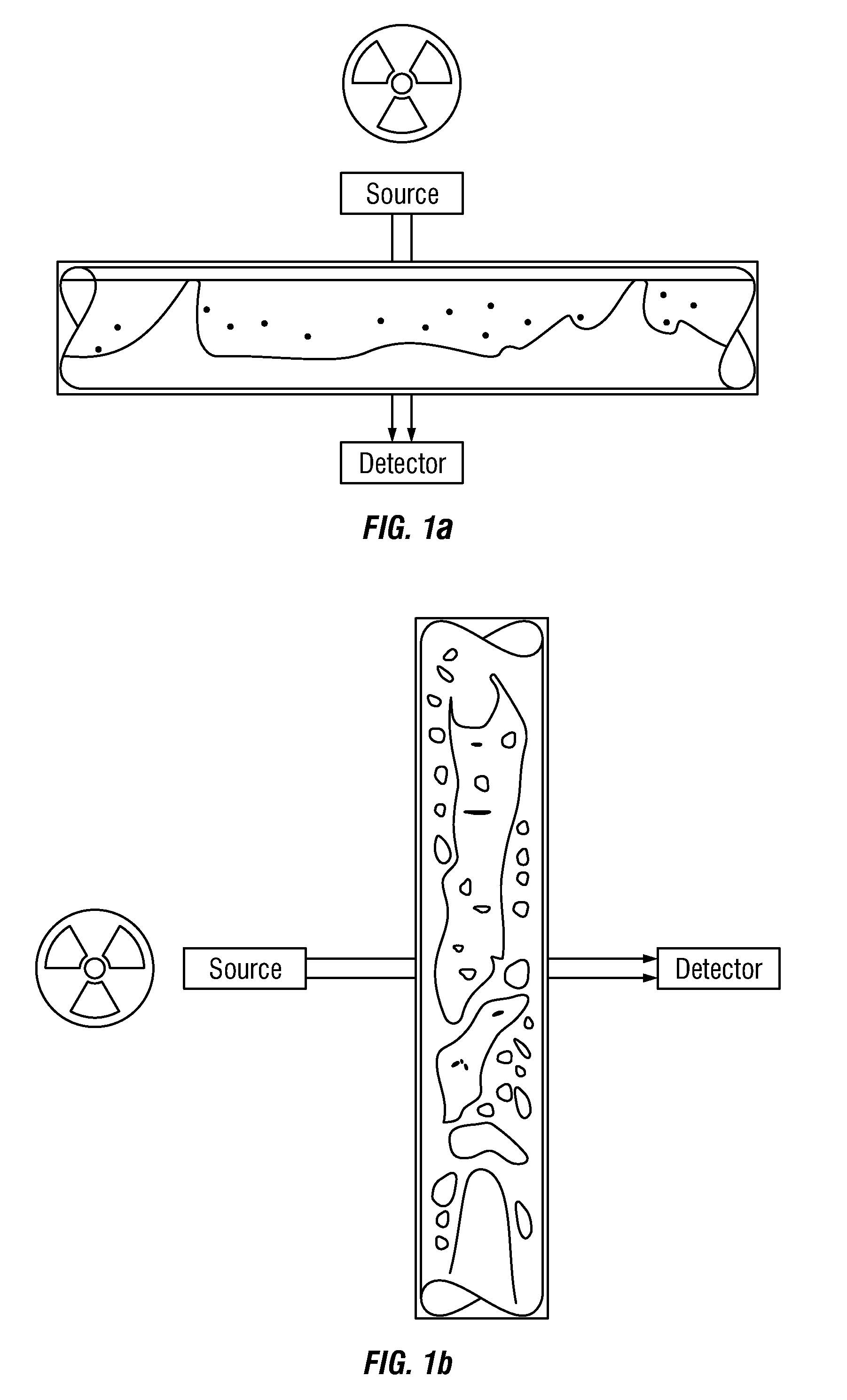
The large variety of flow patterns in which the liquid and gas might be distributed and the variations in the physical properties of each component makes flow rate prediction of each component difficult.
Both of these aspects cause the gas to flow faster than the liquid, or in other words, increase the slip between the gas and liquid.
Because of this, spot density measurement, information regarding slip and thus the corrected bulk-density is lost.
Such methods, however, require rigorous knowledge of the boundary conditions of multiple parameters, such as surface tension, viscosity, fluid mixture, etc.
The slip value in the multiphase fluid produced from a wellbore is sometimes different from such experimentally determined slip values, and thus large errors can result.
Since there is a huge variety of piping configurations and fluid parameter values, using empirically determined slip values will lead to large errors.
Since the above methods make certain assumptions, they may lead to inaccurate results.

Method used


Image

  • Multi-Phase Fluid Measurement Apparatus and Method
  • Multi-Phase Fluid Measurement Apparatus and Method
  • Multi-Phase Fluid Measurement Apparatus and Method

Examples


Embodiment Construction

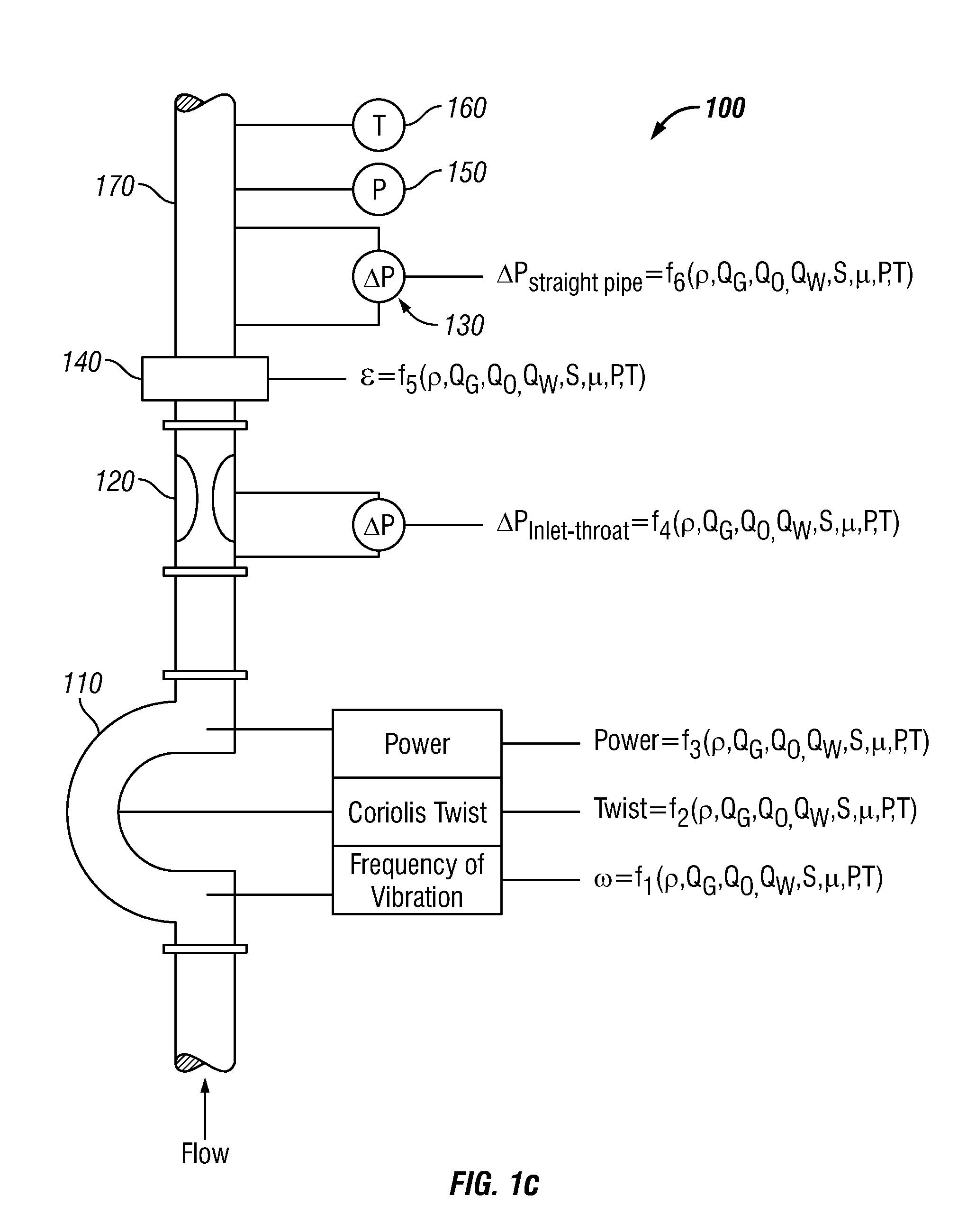
[0028]In one aspect, the system described herein measures the bulk density and flow of a multi-phase flow stream in real-time and utilizes simultaneous equations to correct for the slip, which slip is common in both the density and fluid flow measurements. In another aspect, the system may utilize another independent flow meter to increase the number of equations to allow for the use of a wider band of flow conditions. In another aspect, additional measurements of power, viscosity etc. may be made to increase the number of simultaneous equations, and hence the accuracy of the multi-phase flow calculations.

[0029]FIG. 1c is a schematic diagram of a multi-phase flow measuring system 100 according to one embodiment of the disclosure. The system 100 is shown to include a Coriolis meter 110 to measure in-situ the density of the fluid 102 flowing through the meter 110 by measuring the natural frequency of oscillation of the tubes inside the meter 110. In one aspect, the power and frequency...


PUM


Abstract

The present disclosure provides a flowmeter including a vibrating element configured to be inserted in a measured fluid; a driver circuit to vibrate the vibrating element in its natural frequency of oscillation; one or more additional technology flow meters configured to measure an additional property of the fluid; a data acquisition circuit configured to measure signals effected by the flow of a multi-phase fluid; and a computer suitable to solve non-linear simultaneous equations. The fluid may include gas, oil and / or water. The fluid may also include solids.

Description

CROSS REFERENCE TO RELATED APPLICATIONS[0001]The present application claims priority from U.S. Provisional Application Ser. No. 61 / 175, 370, filed May 4, 2009.BACKGROUND[0002]1. Field of the Disclosure[0003]This disclosure relates generally to multiphase flow measurements of wellbore fluids.[0004]2. Description of the Related Art[0005]Wellbore fluids often are multi-phase fluids that contain oil, gas and water. The composition, flow rate, and viscosity of each component (oil, water, and gas) vary from well to well. Usually, the flow rate of the gas is the fastest and that of the oil the slowest, unless the fluid is well-mixed and gas is entrained inside the liquid. The large variety of flow patterns in which the liquid and gas might be distributed and the variations in the physical properties of each component makes flow rate prediction of each component difficult.[0006]At low fluid velocities, wellbore liquids tend to accumulate at low pockets in horizontal pipes while gas coalesce...

Claims


Application Information

Patent Timeline
Patent Type & Authority Applications(United States)
IPC IPC(8): E21B47/00
CPCG01F1/44G01F1/74G01F1/8436G01F5/00G01F1/86G01F1/88G01F1/8472
Inventor AGAR, JORAMSIDDAVARAM, VIKRAM
Owner AGAR CORP
Learn More