
Disc Brake for a Commercial Vehicle

Active Publication Date: 2010-11-11
KNORR-BREMSE SYST FUER NUTZFAHRZEUGE GMBH
View PDF14 Cites 15 Cited by
  • Summary
  • Abstract
  • Description
  • Claims
  • Application Information

AI Technical Summary

Benefits of technology

[0017]A further major advantage of the invention is that the enhanced comfort of the disc brake can be achieved without additional cost, as compared to the damping bushings used hitherto, which is especially noteworthy if account is taken, in particular, of the series production of the

Problems solved by technology

However, these known damping bushings are not suitable for dealing adequately with the various demands in mobile operation, in particular with regard to shocks that a

Method used


Image

  • Disc Brake for a Commercial Vehicle
  • Disc Brake for a Commercial Vehicle
  • Disc Brake for a Commercial Vehicle

Examples


Example

DETAILED DESCRIPTION OF THE DRAWINGS

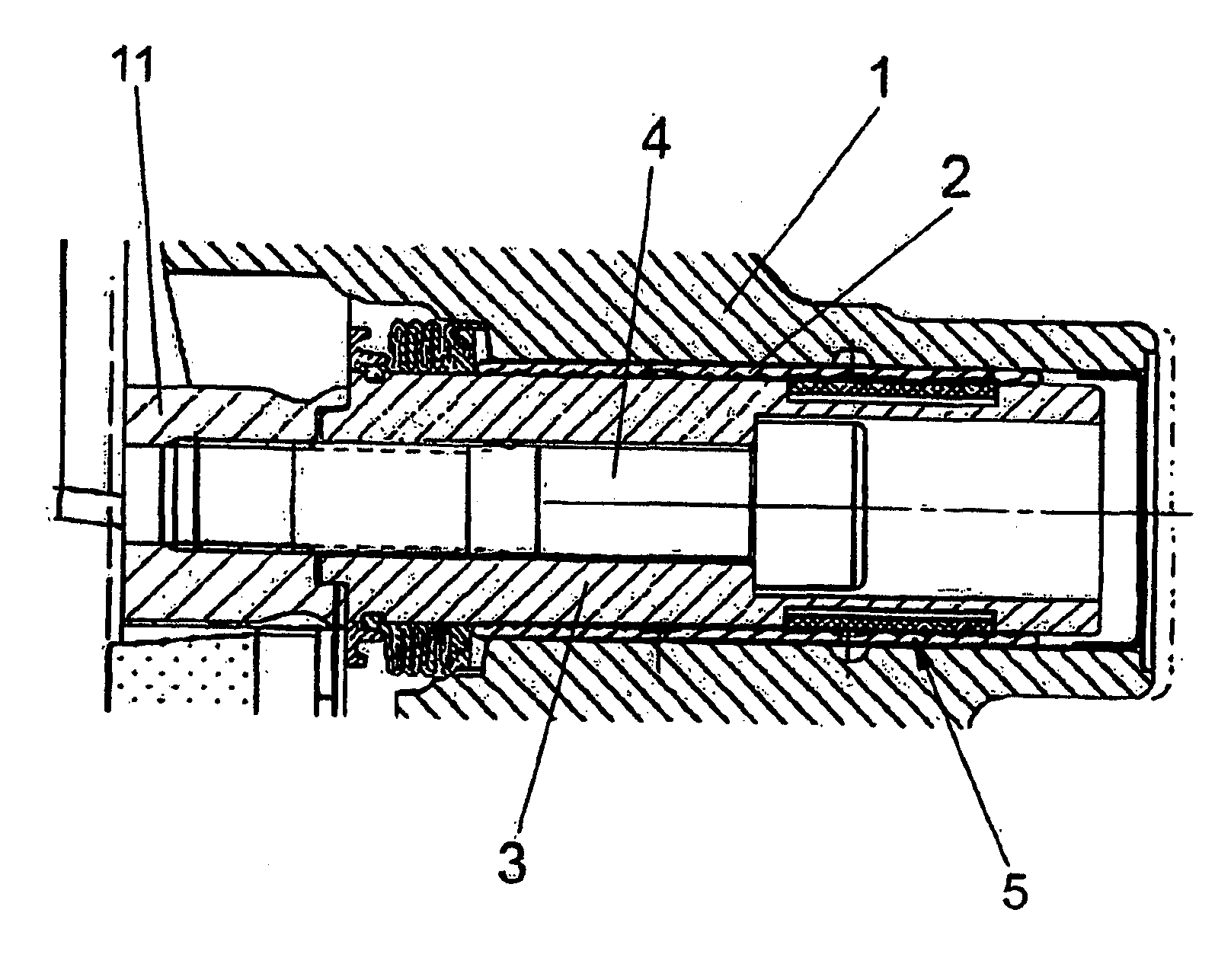
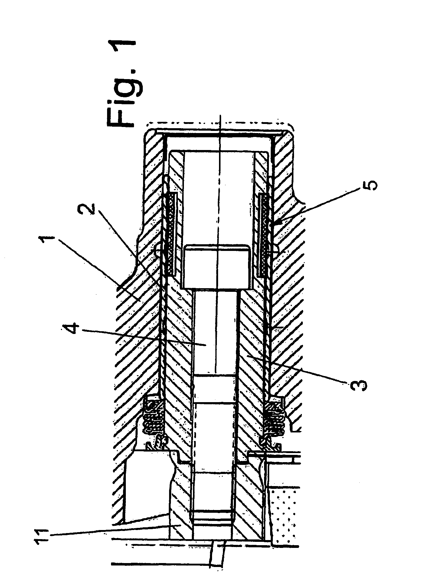
[0027]FIG. 1 shows a part of a disc brake, in particular for a commercial vehicle, having a caliper 1 that straddles a brake disc (not shown) and is fastened by way of two connecting bearings to a brake carrier 11 in an axially displaceable manner in relation to the brake disc.

[0028]In this case, the connecting bearings each have a guide bar 3. The guide bar 3 is rigidly connected to the brake carrier 11. One of the two guide bars 3 is guided in a slide bearing configured as a movable bearing, and the other in a slide bearing configured as a fixed bearing. This allows for the axial displaceability of the caliper 1 in a sliding caliper type of disc brake. Only the region of the fixed bearing is shown in the exemplary embodiment of FIG. 1.

[0029]The guide bar 3 is mounted in a bearing bush 2, which is fastened in the caliper 1 and is made of a material suitable for a slide bearing. The bearing bush 2 slides on the guide bar 3 upon actuation of the di...


PUM


Abstract

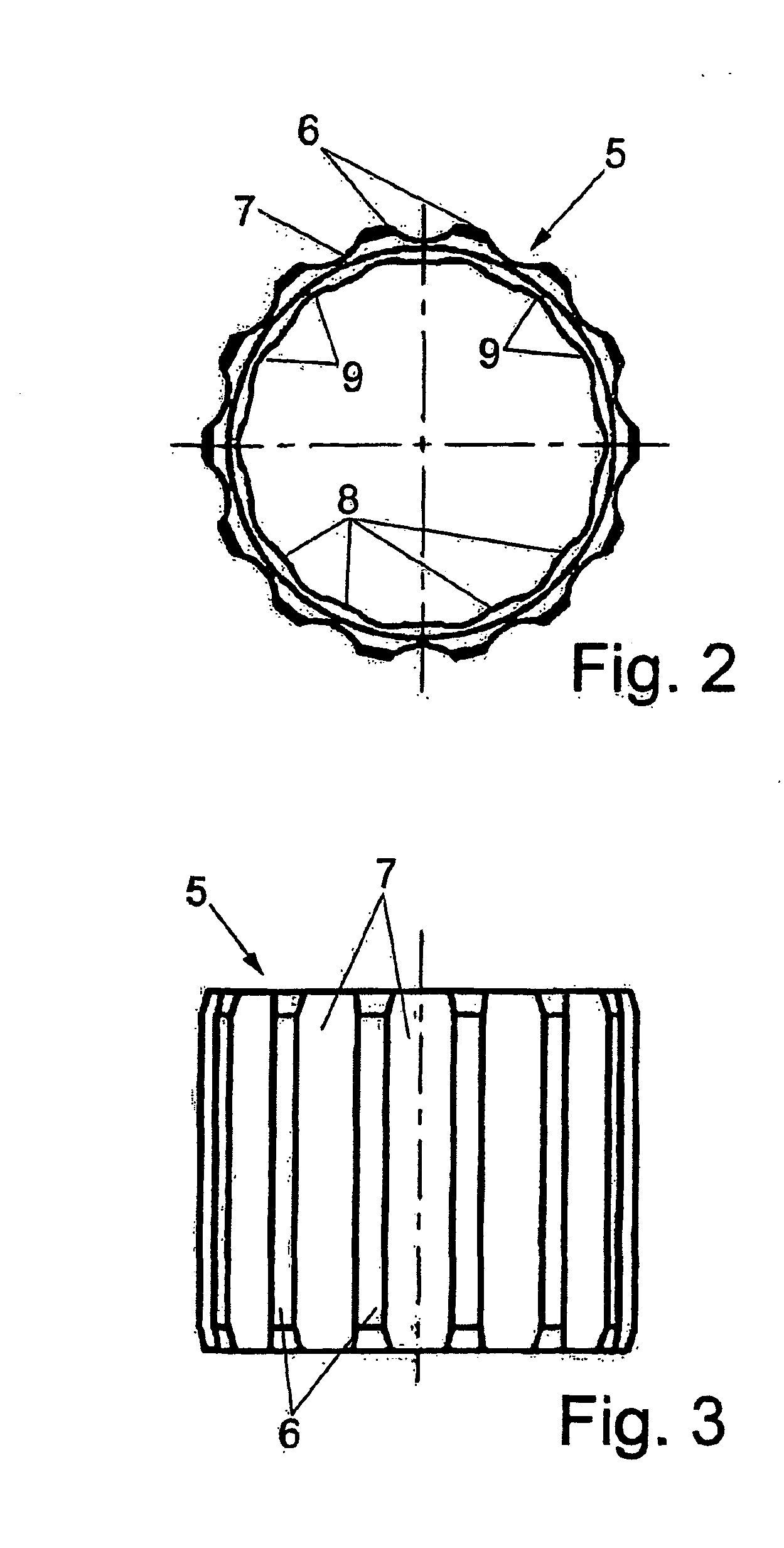
A disc brake for a commercial vehicle has a caliper that straddles a brake disc. The caliper is mounted on a brake carrier on the vehicle side by way of two connecting bearings in an axially displaceable manner in relation to the brake disc. The connecting bearings each include a guide bar that is securely connected to the brake carrier and guided in a slide bearing of the caliper for the axial displacement thereof. At least one connecting bearing is provided with a radially elastic damping bushing, which at least surrounds the guide bar in regions and has grooves that are laterally delimited by ribs. The disc brake is designed such that the damping bushing has a progressive damping behavior in the radial loading direction.

Description

CROSS-REFERENCE TO RELATED APPLICATIONS[0001]This application is a continuation of PCT International Application No. PCT / EP2008 / 009366, filed Nov. 6, 2008, which claims priority under 35 U.S.C. §119 from German Patent Application No. DE 10 2007 053 902.0, filed Nov. 9, 2007, the entire disclosures of which are herein expressly incorporated by reference.BACKGROUND AND SUMMARY OF THE INVENTION[0002]The invention relates to a disc brake for a commercial vehicle having a caliper that straddles a brake disc and is fastened in an axially displaceable manner in relation to the brake disc by two connecting bearings to a brake carrier arranged on the vehicle side. The connecting bearings each have a guide bar, which is rigidly connected to the brake carrier and is guided in a slide bearing of the caliper for axial displacement thereof.[0003]In disc brakes of the concerned type, which are known by the term sliding-caliper disc brakes, the caliper is connected to the brake carrier on the vehic...

Claims


Application Information

Patent Timeline
IPC IPC(8): F16D55/22
CPCF16F1/3835F16D55/22655
Inventor FISCHER, RUDOLFRAFFIN, CHRISTIANPESCHEL, MICHAELORGLER, FLORIAN
Owner KNORR-BREMSE SYST FUER NUTZFAHRZEUGE GMBH
Learn More