Eureka AIR delivers breakthrough ideas for toughest innovation challenges, trusted by R&D personnel around the world.

Device for comminuting input material

a technology of input material and comminuting machine, which is applied in cocoa, grain treatment, food science, etc., can solve the problems of disproportionately large amount of work that can be performed with relatively small machines, and achieve qualitatively superior processing of input materials and intensive processing

Inactive Publication Date: 2010-11-11
PALLMANN MASCHFAB GMBH & CO KG
View PDF12 Cites 12 Cited by
  • Summary
  • Abstract
  • Description
  • Claims
  • Application Information

AI Technical Summary

Benefits of technology

[0010]It is therefore an object of the present invention to provide a pin mill that permits a more intensive and qualitatively superior processing of the input material compared with the state of the art.
[0011]Since the comminuting pins are subject to extensive wear because of the impact of the input material and therefore must be changed frequently, an additional task of the invention includes minimizing the down times of a device by providing for easy and rapid replacement of the comminuting pins insofar as possible.
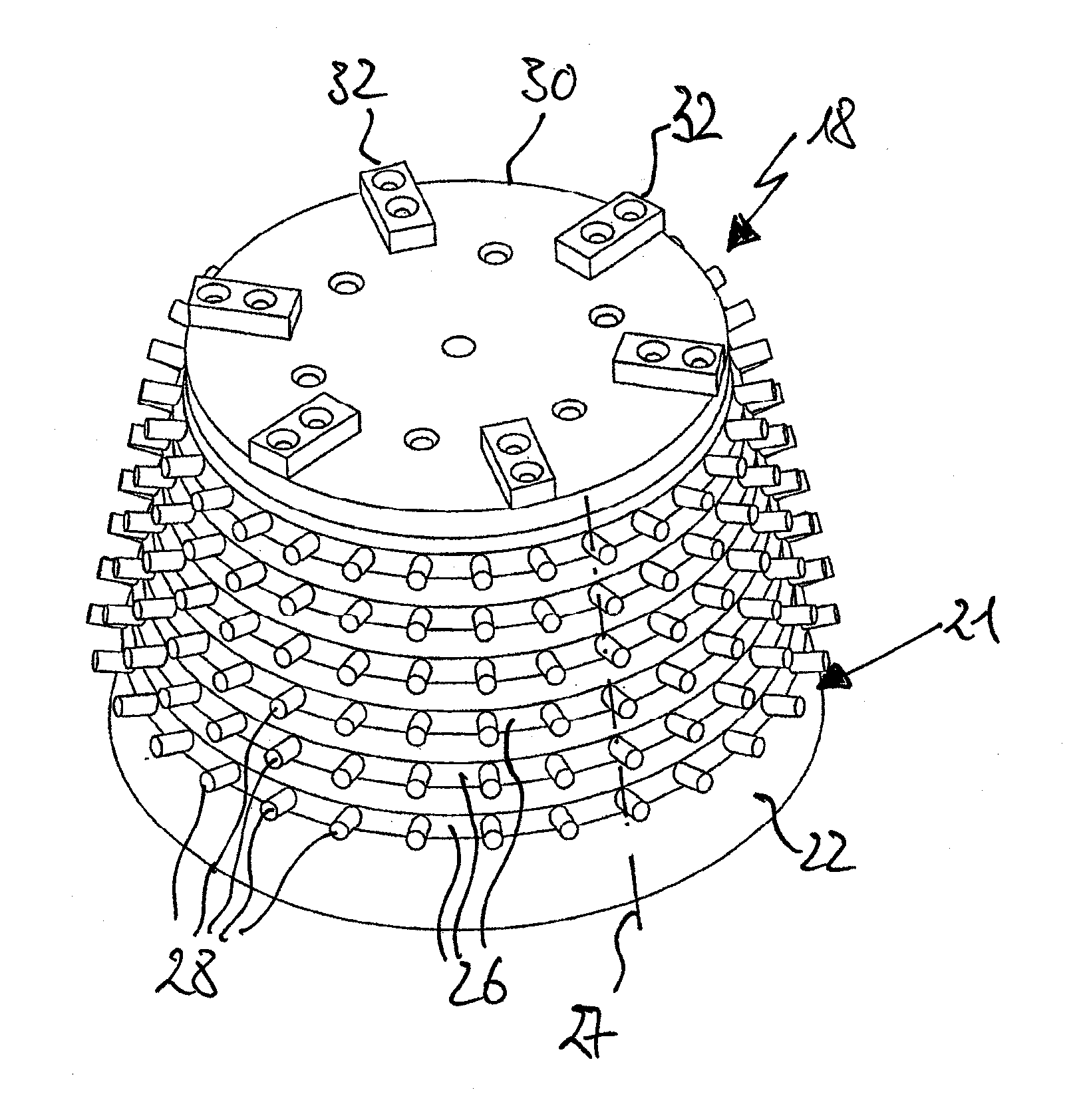
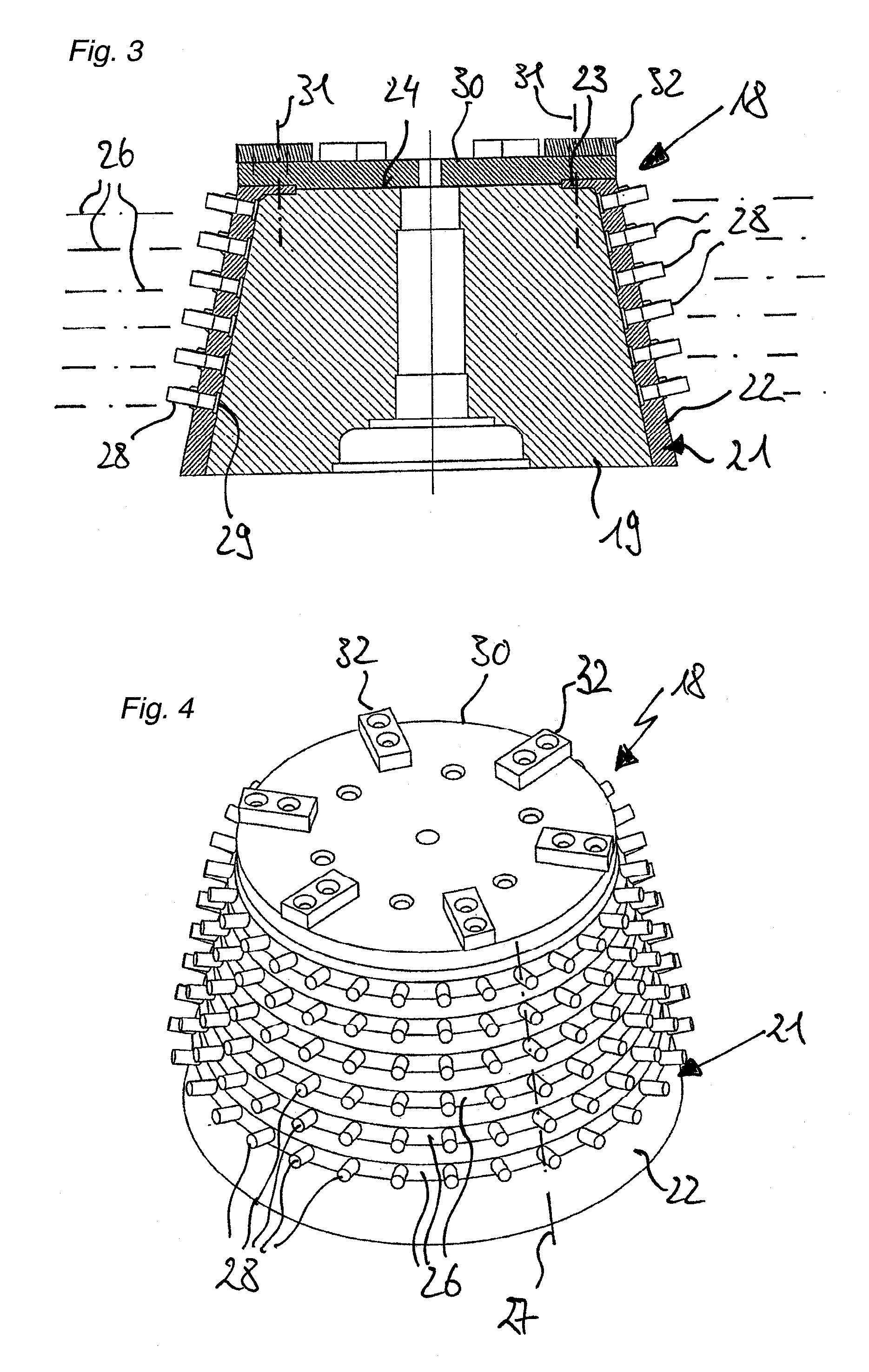
[0012]The invention breaks away from the common concept of a two-dimensional comminution zone in pin mills and provides for the first time for making a three-dimensional comminution zone. This is done according to the invention by using a cylindrical or conical rotor, which is fitted over its circumference with first pin-shaped comminution tools. In this way a high pin density can be attained within the comminution zone with only slight enlargement of the housing. Therefore, disproportionately large amounts of work can be performed with relatively small machines.

Problems solved by technology

Therefore, disproportionately large amounts of work can be performed with relatively small machines.

Method used


Image

  • Device for comminuting input material
  • Device for comminuting input material
  • Device for comminuting input material

Examples


Embodiment Construction

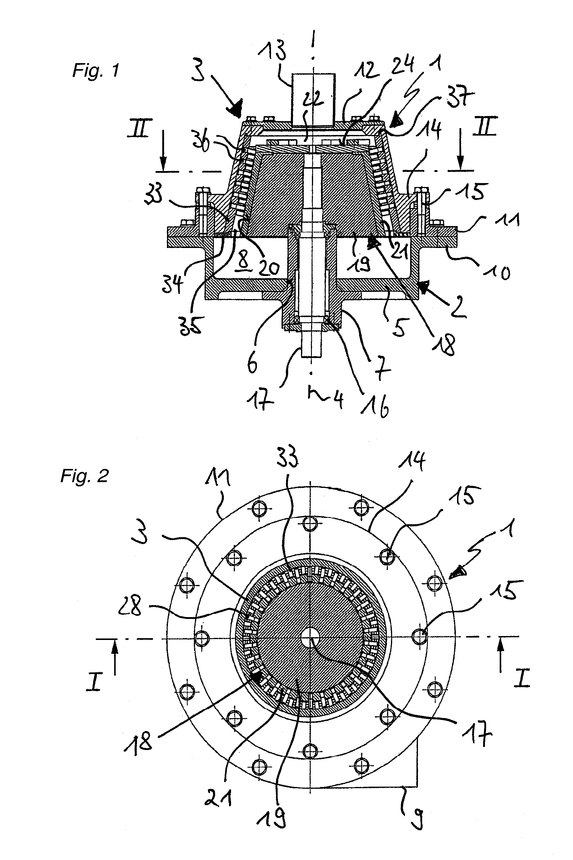
[0031]The general structure of a device according to the invention is apparent from FIGS. 1 and 2. The figures show a housing 1, which is made up of a cylindrical lower piece 2 and a bell-shaped upper piece 3. The longitudinal axis of the housing 1 is provided with the reference symbol 4. The lower piece 2 is closed off downward by a base 5, in which a circular opening 6 is disposed concentric to the shaft 4. Opening 6 serves to receive an essentially cylindrical shaft bearing 7, which is screwed onto the base 5 coaxially to the shaft 4 with a flange connection. The upper end of the shaft bearing 7 extends into the area of the upper piece 3. In this way, within the lower piece 2, an annular channel 8 is formed, which opens over a material outlet 9 from the housing 1 that runs tangentially to the shaft 4. The upper terminus of the bottom piece 2 forms a circumferential annular flange 10, to which a support ring 11 of angular cross-section is fastened.

[0032]As was previously mentioned...


PUM


Abstract

A device for comminuting input material, especially for fine and ultrafine grinding of input material, includes a rotor revolving around a shaft inside a housing, the rotor having a cylindrical or conical jacket surface. An annular gap is present between the housing and the jacket surface, the gap forming a comminution zone and the input material being introduced axially to it. To increase the economic efficiency of the device, it is provided that a plurality of first pin-shaped comminuting tools for comminuting the input material are disposed over the circumference of the rotor, wherein the tools are aligned with their longitudinal direction perpendicular to the jacket surface in the direction of the housing.

Description

[0001]This nonprovisional application claims priority under 35 U.S.C. §119(a) to German Patent Application No. DE 10 2009 020 708.2, which was filed in Germany on May 11, 2009, and which is herein incorporated by reference.BACKGROUND OF THE INVENTION[0002]1. Field of the Invention[0003]The invention relates to a device for comminuting input.[0004]2. Description of the Background Art[0005]Comminution devices are used primarily for comminution of input material by impact or striking, wherein comminution down to very fine grinding is possible. For example, devices of this class are used in the food industry for fine grinding of fat-containing beans, such as cacao or coffee, or beating and homogenizing fruit pulps. In the chemical industry, devices of this class are used, for example, for producing pigments or grinding polymers. The comminution of soft-elastic materials such as rubber or used tire granules is also possible, generally in conjunction with the introduction of cooling power...

Claims


Application Information

Patent Timeline
Patent Type & Authority Applications(United States)
IPC IPC(8): B02C13/22
CPCB02C13/28B02C13/22
Inventor PALLMANN, HARTMUT
Owner PALLMANN MASCHFAB GMBH & CO KG
Why Eureka
Eureka Blog
Learn More