
Stabilizing Assembly of Drawable Carrier

Active Publication Date: 2010-11-11
CHEN TSUNG YAO
View PDF12 Cites 47 Cited by
  • Summary
  • Abstract
  • Description
  • Claims
  • Application Information

AI Technical Summary

Benefits of technology

[0005]For solving the problem of disengagement and aberration between the slide guide and the drawable carrier that lead to or unstable sliding of the drawable carrier, the present invention provides a retaining device settled between a cabinet body and a drawable carrier. The retaining device prevents the drawable carrier from sliding bias and causing noise due to jogging or disengaging gears in sliding of the drawable carrier.
[0008]In addition to orienting and stabilizing the sliding drawable carrier, the present invention also, in virtue of the radial limitation the stop unit provides to the bushes, eliminates disengagement between the gears and racks even when the drawable carrier receives an unbalanced drawing or pushing force while ensuring smooth and stable slide of the drawable carrier, and preventing sliding noise and jogging.

Problems solved by technology

However, since sliding rails and sliding guides are usually assembled with intervals of considerable width therebetween, when a pulling or pushing force is exerted on any point of the drawer except the center of the facade of the drawer, the drawer slides bias, leading to abnormal operation and thus wear of the drawer, eventually reducing the service life of the drawer.
However, when the drawable carrier, especially in the case where the drawable carrier is a large drawer, is drawn or pushed under an extremely transversely unbalanced force, the gears are liable to escape from the row holes, causing the drawable carrier aberrant.
Such aberration not only brings about sliding noise, but also leads to accelerative wear of the gears and the row holes, or, even forces the two side gears to jump out of the row holes, incurring damage to the structural components.

Method used


Image

  • Stabilizing Assembly of Drawable Carrier
  • Stabilizing Assembly of Drawable Carrier
  • Stabilizing Assembly of Drawable Carrier

Examples


Embodiment Construction

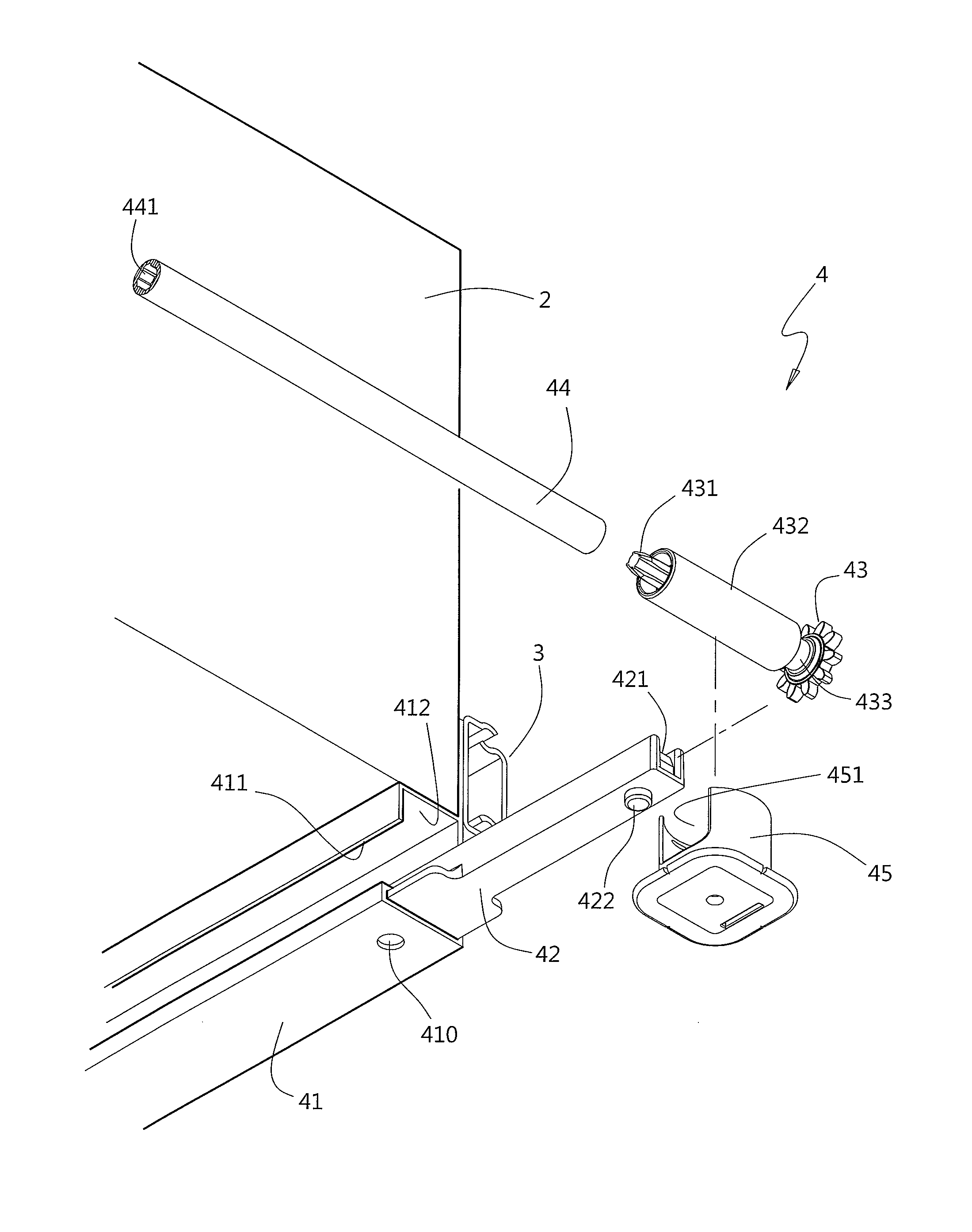
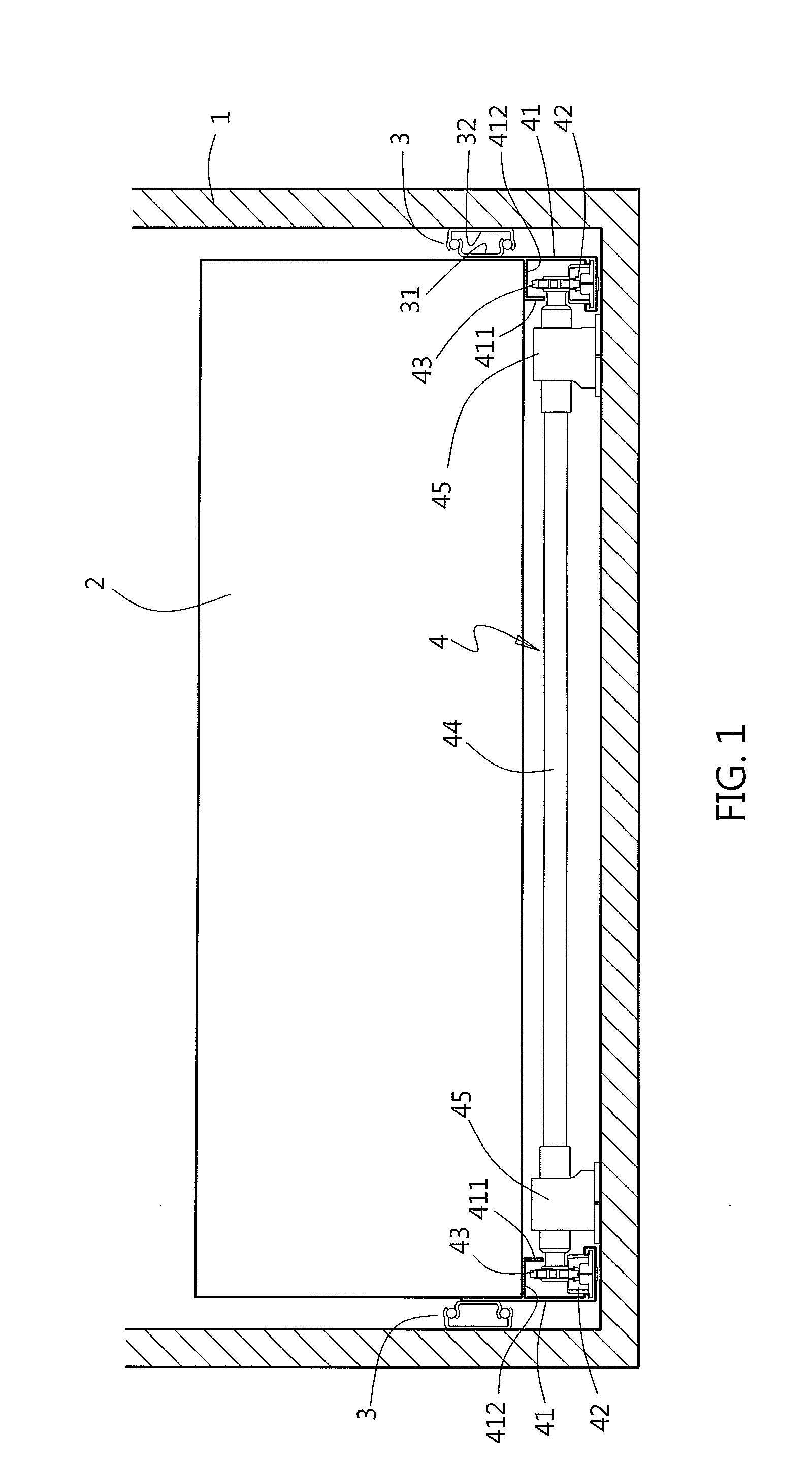
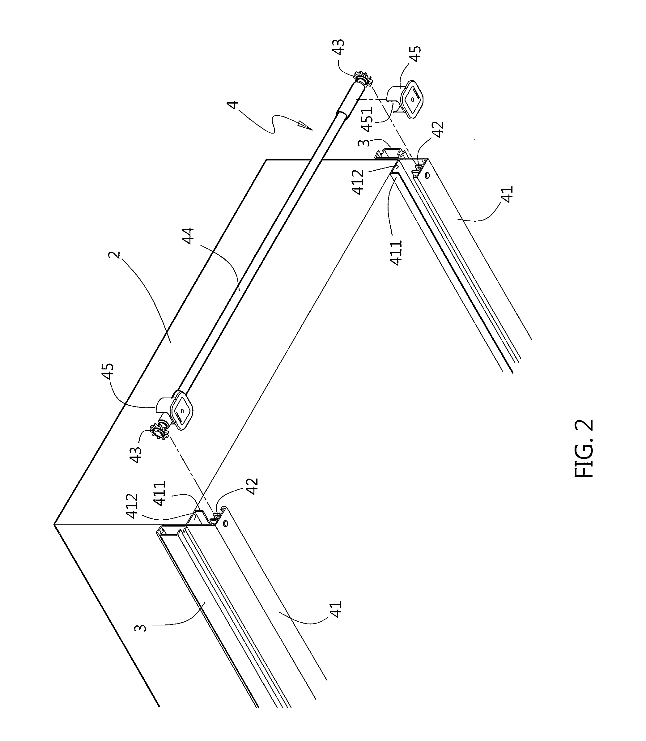
[0020]The present invention provides a stabilizing assembly of drawable carrier. Referring to FIGS. 1 through 4, a cabinet body 1 is installed with a predetermined number of drawable carriers (such as drawers, baskets, shelves, etc.), as one said drawable carrier 2 is provided in the presently shown embodiments. The drawable carrier 2 is configured to be pushed or drawn to slide into or out from the cabinet body 1. For this end, a drawer slide 3 is provided between each of two laterals of the drawable carrier 2 and the cabinet body 1. The drawer slide 3 includes a guiding member 31 fixed to the drawable carrier 2 and a sliding rail 32 fixed to the cabinet body 1 correspondingly so that the guiding member 31 and the sliding rail 32 mutually engage in a slidable and longwise extendable manner. In addition, a retaining device 4 is provided between a bottom of the drawable carrier 2 and the cabinet body 1. The retaining device 4 is composed of two rails 41 fixed to two laterals of the d...


PUM


Abstract

A stabilizing assembly includes a retaining device settled between a drawable carrier and a cabinet body for preventing the drawable carrier from swinging in sliding. The retaining device includes two rails fixed to two opposite laterals of the drawable carrier. Each of the rails has a rack. Two gears engaging with the racks are connected by a rod and rotate simultaneously. Two bushes at two ends of the rod are received in supporting seats that are fixed on the cabinet body or the drawable carrier and allowed to shift vertically. Two stop portions, as a stop unit, each extending from the rail toward a side of the rod opposite to another side of the rod facing the rack on the rail are closely adjacent to the retained portions so that the bushes are retained and stopped by the stop unit, and disengagement between the racks and the gears is prevented.

Description

FIELD OF THE INVENTION[0001]The present invention relates to a structural assembly for orienting and stabilizing a drawable carrier so as to not only prevent the drawable carrier from sliding bias and swinging but also eliminate noise caused by jogging or disengaging gears when the drawable carrier is pushed or drawn to slide.BACKGROUND OF THE INVENTION[0002]Generally, between a cabinet body and a drawer installed therein, there are drawer slides composed of sliding rails and sliding guides for easy and smooth slide of the drawer inward or outward the cabinet body. However, since sliding rails and sliding guides are usually assembled with intervals of considerable width therebetween, when a pulling or pushing force is exerted on any point of the drawer except the center of the facade of the drawer, the drawer slides bias, leading to abnormal operation and thus wear of the drawer, eventually reducing the service life of the drawer.[0003]For remedying this problem, the inventor of the...

Claims


Application Information

Patent Timeline
IPC IPC(8): A47B88/12A47B88/49A47B88/493
CPCA47B88/14A47B2210/0067E05Y2201/706E05Y2201/62A47B2210/0078A47B88/45A47B88/487
Inventor CHEN, TSUNG YAO
Owner CHEN TSUNG YAO
Learn More