Light-emitting unit and backlight apparatus having the same

a backlight and light-emitting technology, applied in lighting and heating apparatus, static indicating devices, instruments, etc., can solve the problems of thick display panel, high luminance needs to be used, dark screen as compared with direct lighting, etc., and achieve the effect of brighter screen

Inactive Publication Date: 2010-11-11
SAMSUNG ELECTRONICS CO LTD
View PDF18 Cites 16 Cited by
  • Summary
  • Abstract
  • Description
  • Claims
  • Application Information

AI Technical Summary

Benefits of technology

[0011]One or more exemplary embodiments provide a backlight apparatus to provide a slim display device and bright light, and a light source unit used for the backlight apparatus so as to solve the disadvantages of edge lighting and direct lighting.
[0020]As can be appreciated from the above description, a backlight apparatus having a slimmer design as compared with direct lighting, and a brighter screen as compared with edge lighting can be provided.

Problems solved by technology

However, comparatively expensive LEDs having high luminance have to be used, and the amount of light lost by diffusion results in a darker screen as compared with direct lighting.
However, since LEDs are disposed on the back of the display panel, the display panel is thick.
Also, exemplary embodiments are not required to overcome the disadvantages described above, and an exemplary embodiment may not overcome any of the problems described above.

Method used


Image

  • Light-emitting unit and backlight apparatus having the same
  • Light-emitting unit and backlight apparatus having the same
  • Light-emitting unit and backlight apparatus having the same

Examples


Embodiment Construction

[0030]Certain exemplary embodiments will now be described in greater detail with reference to the accompanying drawings.

[0031]In the following description, like drawing reference numerals are used for like elements, even in different drawings. The matters defined in the description, such as detailed construction and elements, are provided to assist in a comprehensive understanding of the invention. However, the exemplary embodiments can be practiced without those specifically defined matters. Also, well-known functions or constructions are not described in detail since they would obscure the invention with unnecessary detail.

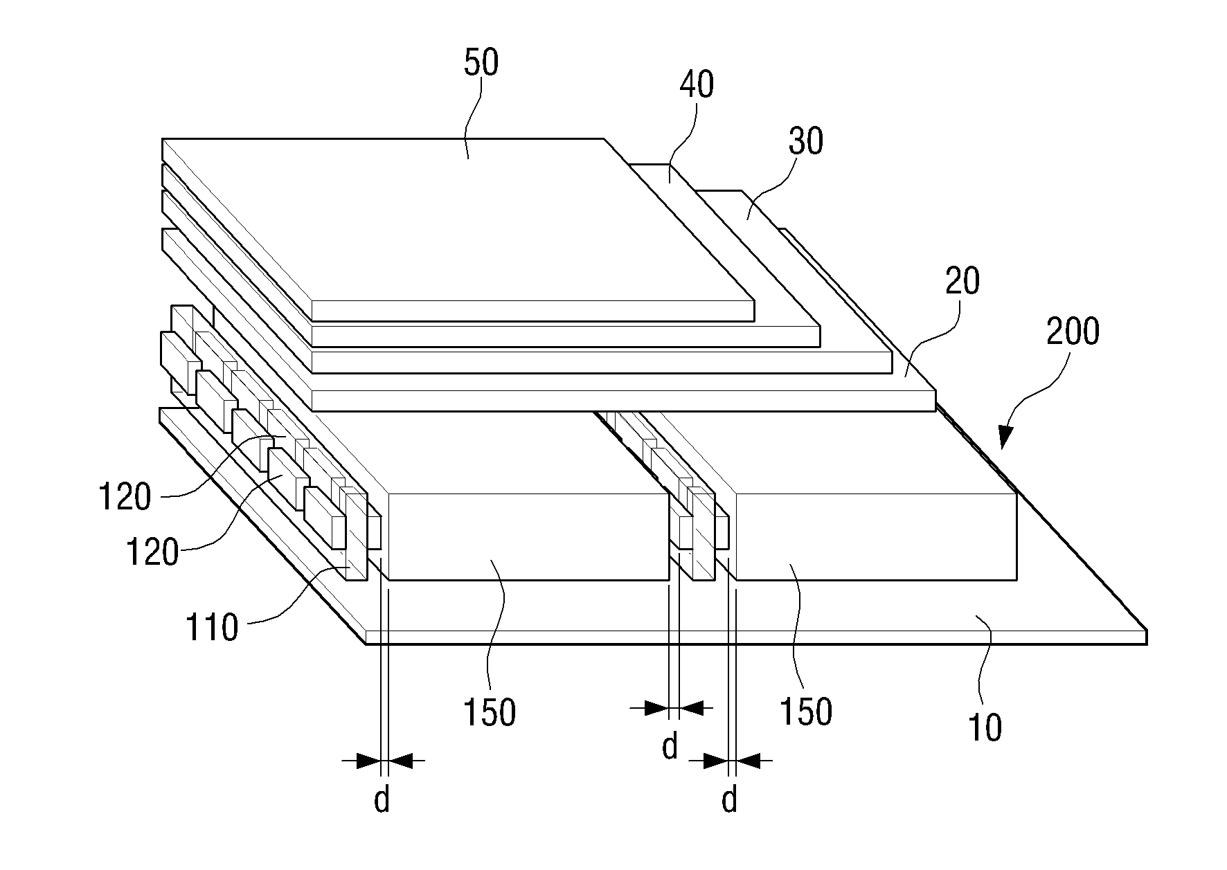
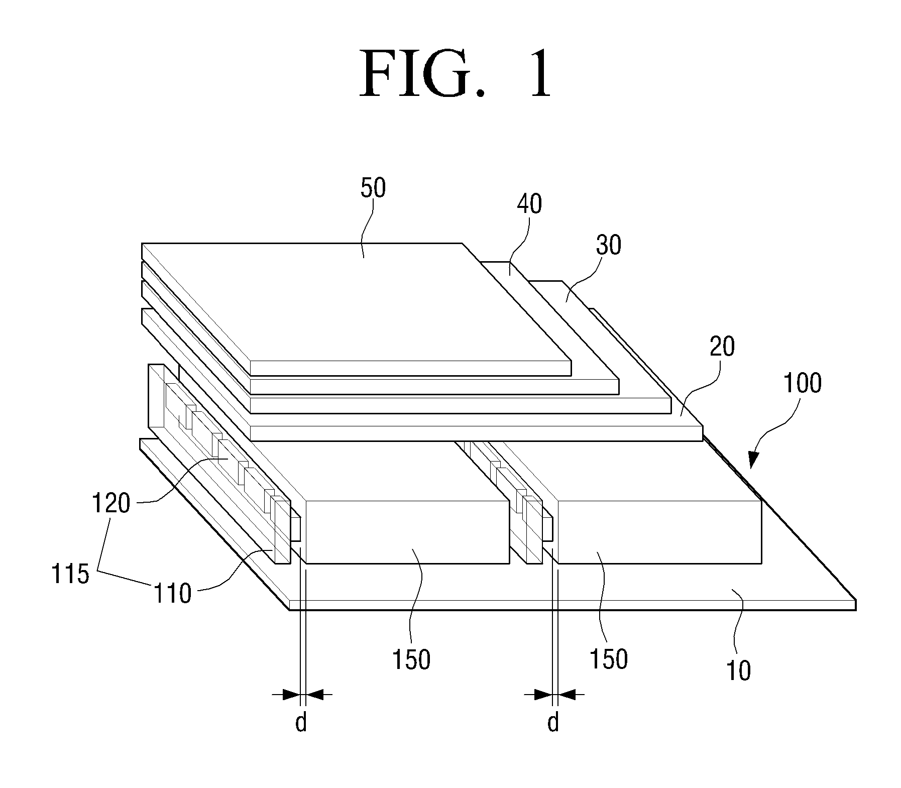
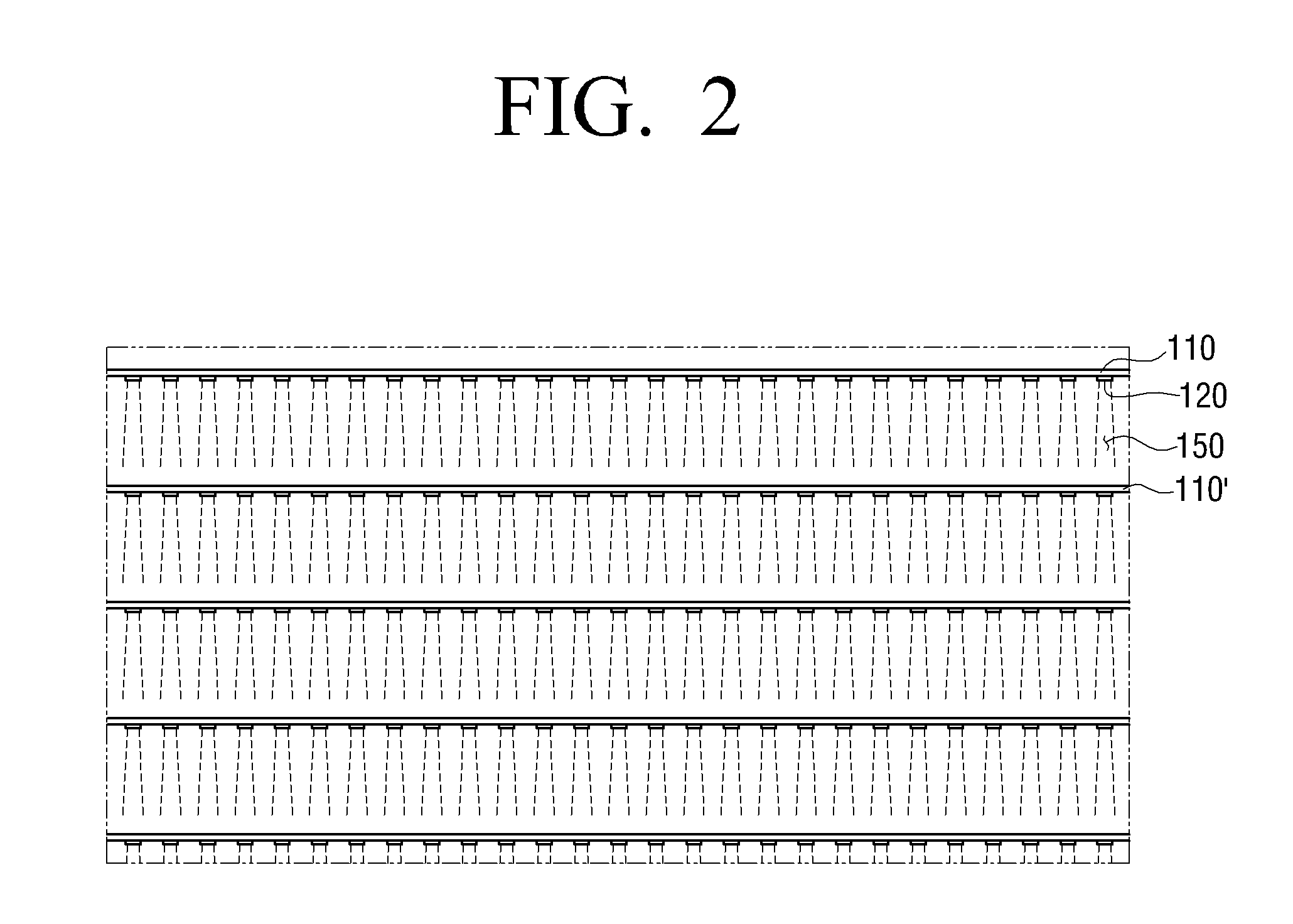
[0032]FIGS. 1 and 2 illustrate a backlight apparatus according to a first exemplary embodiment. The backlight apparatus according to the first exemplary embodiment of the present invention may include a reflection sheet 10, a light source unit 100, a polarizing plate 20, a polarizing sheet 30, a band elimination filter (BEF) 40, and a dual brightness enhancement...


PUM


Abstract

A light source unit is provided that includes a plurality of transparent substrates on which a plurality of light sources are mounted and which are arranged in a plurality of rows. A plurality of light guide plates (LGPs) are interposed between the plurality of transparent substrates, wherein the light source emits light so that the light penetrates the LGP and faces the transparent substrate at a next row.

Description

CROSS-REFERENCE TO RELATED APPLICATIONS[0001]This application claims priority from Korean Patent Application No. 10-2009-0040763, filed on May 11, 2009 in the Korean Intellectual Property Office, the disclosure of which is incorporated herein by reference in its entirety.BACKGROUND[0002]1. Field of the Invention[0003]Apparatuses and methods consistent with the inventive concept relate to a backlight apparatus, and more particularly, to a backlight unit which is used for a flat panel display using a thin film transistor-liquid crystal display (TFT-LCD) panel such as a monitor and a television.[0004]2. Description of the Related Art[0005]Since display elements such as TFT-LCDs are not light-emitting elements, a backlight for emitting light is needed. A cold cathode fluorescent lamp (CCFL) has been used as a backlight, but recently the use of a light-emitting diode (LED) has been increasing due to its advantages of weight, thickness, power consumption, color gamut, switching time, and ...

Claims


Application Information

Patent Timeline
Patent Type & Authority Applications(United States)
IPC IPC(8): G09G3/36F21V7/04
CPCG02B6/0068G02B6/0091G02B6/0088G02B6/0073G02F1/1335
Inventor CHOI, SUK-JULEE, KYE-HOONKIM, KYOUNG-AE
Owner SAMSUNG ELECTRONICS CO LTD
Why Eureka
Try Eureka