Determining biological tissue optical properties via integrating sphere spatial measurements

a spatial measurement and optical property technology, applied in the field of optical instruments, can solve the problems of destroying all spatial information from a sample, no way of determining spatial data within an integrating sphere, and the limitations of the integrating sphere currently available, and achieve the effect of readily determining the optical properties of biological tissu

Inactive Publication Date: 2010-11-11
UT BATTELLE LLC
View PDF7 Cites 14 Cited by
  • Summary
  • Abstract
  • Description
  • Claims
  • Application Information

AI Technical Summary

Benefits of technology

[0009]The optical properties of tissue are determined by collecting spatial reflectance data from a biological tissue using an integrating sphere. An automated positional light-occlusion apparatus is employed to provide a spatial measure of reflectance. The apparatus can be controlled by an automated program to receive and manipulate raw reflectance data, and convert this data to the optical properties of a sample using oblique-incidence theory. Positional information can be measured using an integrating sphere. The optical properties of biological tissue is readily determined by using an integrating sphere, accurately and economically, by an automated method.

Problems solved by technology

However, this advantage also comes with the disadvantage of destroying all spatial information from a sample.
As such, there is currently no way of determining spatial data within an integrating sphere.
Further, the integrating sphere currently available suffers from a few limitations.
However, the process of microtome takes time and expense.
As a consequence, the measured optical properties of a sample prepared by microtome can deviate from the true optical properties of an undamaged sample by the artifacts of the structural damage introduced into the prepared sample due to the freezing and the mechanical slicing.
Since it is extremely difficult for the user to manually position the sample perfectly by visual inspection alone, the data collected represents an inconsistent measurement of the sample.
Besides the high cost of having to purchase a second integrating sphere, this prior art technique is limited to extremely thin tissue samples, since light must be transmitted into the second integrating sphere for measurement.
Due to the lack of an accurate and economic method for determining optical properties within a standard integrating sphere optical measurement device, translation of optical biomedical devices and technologies from research laboratories to clinics have been hampered.

Method used


Image

  • Determining biological tissue optical properties via integrating sphere spatial measurements
  • Determining biological tissue optical properties via integrating sphere spatial measurements
  • Determining biological tissue optical properties via integrating sphere spatial measurements

Examples


Embodiment Construction

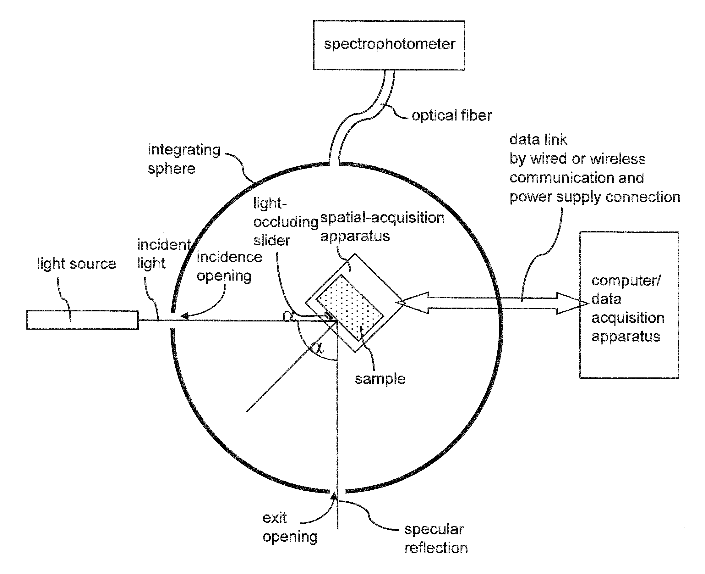
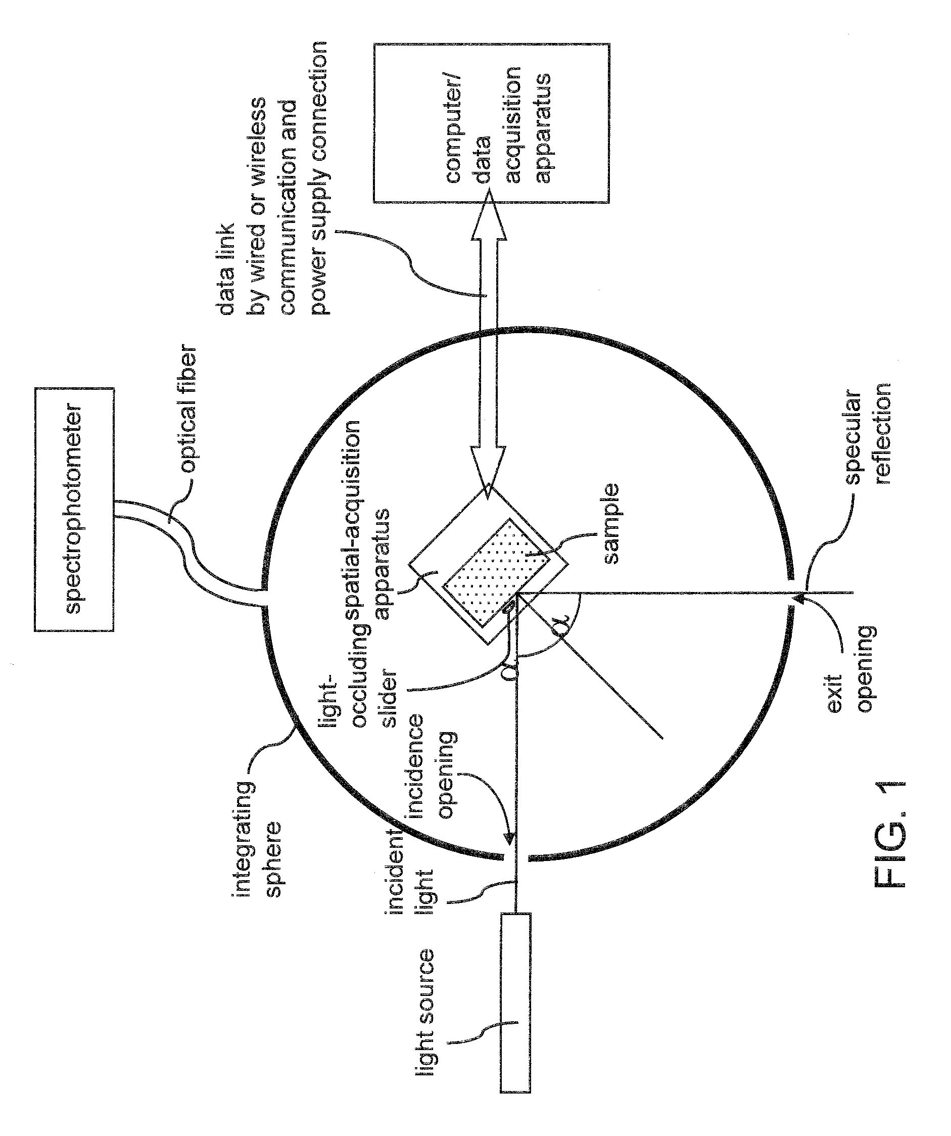
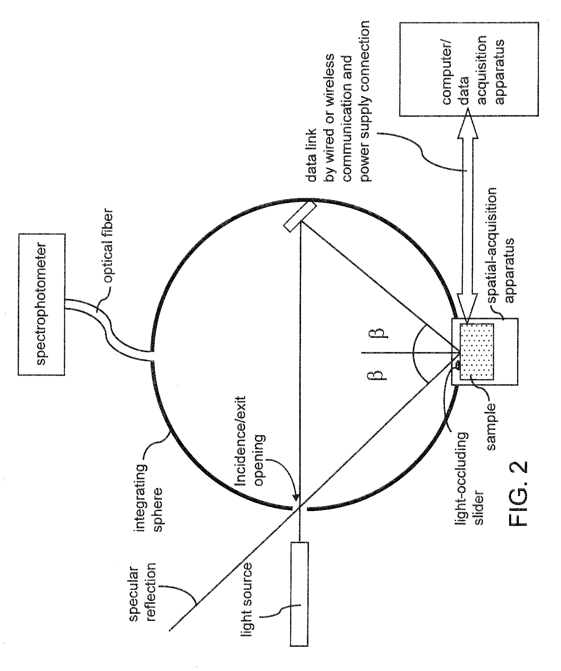
[0036]As stated above, the present invention relates to an optical apparatus, a method of operating the same, and a program to perform the operation of the same. The present invention is now described in detail with accompanying figures. It is noted that like and corresponding elements mentioned herein and illustrated in the drawings are referred to by like reference numerals.

[0037]Referring to FIGS. 1 and 2, a first exemplary optical apparatus and a second exemplary optical apparatus are shown, respectively, in a horizontal cross-sectional view. Each of the first and second exemplary optical apparatus includes an enclosure having a reflective inner surface, a spatial-acquisition apparatus configured to hold a sample on a front side, a light source, a light-occluding slider, a spectrophotometer, a linear motion controller (not shown in FIGS. 1 or 2), a computer, a data acquisition apparatus, and peripheral devices configured to provide data link by wired or wireless communication an...


PUM

PropertyMeasurementUnit
heightaaaaaaaaaa
heightaaaaaaaaaa
diameteraaaaaaaaaa

Abstract

An optical sample is mounted on a spatial-acquisition apparatus that is placed in or on an enclosure. An incident beam is irradiated on a surface of the sample and the specular reflection is allowed to escape from the enclosure through an opening. The spatial-acquisition apparatus is provided with a light-occluding slider that moves in front of the sample to block portions of diffuse scattering from the sample. As the light-occluding slider moves across the front of the sample, diffuse light scattered into the area of the backside of the light-occluding slider is absorbed by back side surface of the light-occluding slider. By measuring a baseline diffuse reflectance without a light-occluding slider and subtracting measured diffuse reflectance with a light-occluding slider therefrom, diffuse reflectance for the area blocked by the light-occluding slider can be calculated.

Description

STATEMENT REGARDING FEDERALLY SPONSORED RESEARCH OR DEVELOPMENT [0001]This invention was made with United States government support under Prime Contract No. DE-AC05-00OR22725 awarded by the U.S. Department of Energy. The United States government has certain rights in this invention.FIELD OF THE INVENTION [0002]The present invention relates to the field of optical measurement, and specifically to an optical apparatus, a method of operating the same, and a program to perform the operation of the same.BACKGROUND OF THE INVENTION [0003]Biomedical optics is an emerging field with enormous potential to diagnose and treat diseases safely and economically. Success in application of biomedical optics is highly dependent on accurate characterization of optical properties of target tissues. Particularly, the interaction of a particular type of tissue with light needs thorough and accurate characterization to predict the interaction of light with such a tissue during treatment.[0004]Integrating...

Claims


Application Information

Patent Timeline
Patent Type & Authority Applications(United States)
IPC IPC(8): G01N21/51
CPCG01N21/474G01N2201/065G01N2201/0642
Inventor BABA, JUSTIN S.LETZEN, BRIAN S.
Owner UT BATTELLE LLC
Why Eureka
Try Eureka