Acetabular reamer

a technology of acetabular reamer and reamer, which is applied in the field of surgical devices, can solve the problems of large sterilization cost, damage and injury to soft tissues adjacent to the incision

Inactive Publication Date: 2010-11-11
ECOLE DE TECH SUPERIEURE
View PDF15 Cites 5 Cited by
  • Summary
  • Abstract
  • Description
  • Claims
  • Application Information

AI Technical Summary

Benefits of technology

[0011]In a broad aspect, the invention provides an acetabular reamer for reaming an acetabulum, reaction forces being exerted onto the acetabular reamer by the acetabulum when the acetabulum is reamed, the acetabular reamer comprising: a body, the body defining a rotation axis about which the acetabular reamer is rotatable; a reaming element operatively coupled to the body so as to be movable between a reaming element inner position and a reaming element outer position relatively thereto, the reaming element being positioned further away from the rotation axis in the reaming element outer position than in the reaming element inner position; an actuator operatively coupled to the reaming element for moving the reaming element between the reaming element inner and outer positions; and a reaming element lock configurable between a locked configuration and an unlocked configuration, the reaming element lock being operatively coupled to the reaming element in a manner such that when the reaming element lock is in the unlocked configuration, the reaming element is substantially freely movable by the actuator between the reaming element inner and outer positions, and when the reaming element lock is in the locked configuration, the reaming element lock substantially prevents the reaming element from moving relatively to the body; the reaming element lock being configured, sized and operatively coupled to the reaming element and the body in a manner such that when the reaming element lock is in the locked configuration and the reaction forces are exerted onto the reaming element, a larger portion of the reaction forces is transmitted to the body than to the actuator.
[0012]Advantageously, in some embodiments of the invention, the proposed acetabular reamer includes a relatively large number of reaming elements as the actuator may have a relatively complex configuration while fitting within the relatively small inner space defined by the reaming elements. Indeed, the relatively large reaction forces exerted onto the acetabular reamer when in use are transmitted to the body not through the actuator, but through the reaming element lock. Since the reaming element lock may be configured so as to be relatively sturdy while remaining confined within the surface defined by the reaming elements, the proposed acetabular reamer is relatively sturdy even when including a relatively large number of reaming elements and a relatively fragile actuator.

Problems solved by technology

Each time an instrument is inserted in the patient, or removed therefrom, there is a risk that soft tissues adjacent the incision become damaged by this action.
In turn, this requires that many reaming elements be brought into an operating room, which results in relatively large sterilizing costs.
Furthermore, the repetitive insertion and removal of the acetabular reamer from the patient is time-consuming and may cause injuries to soft tissues adjacent the incision.
Another problem of many conventional acetabular reamers is that the reaming element typically includes asperities that are spaced apart from each other.
Since the surgeon typically does not see the result of this operation, there is always a risk that the resulting surface is not smooth enough and results in sub-optimal implementation of the acetabular cup.
Another disadvantage of this motion is that, once again, it creates a risk of injuring soft tissues inside the patient.
However, in this acetabular reamer, when the arcuately-shaped segments are moved away from the central location, the arcuately-shaped segments become spaced apart from each other, which therefore create gaps therebetween.
This leads to a restriction to a relatively small number of the number of arcuately-shaped segments that can be provided because of size limitations present in such reamers.
A disadvantage of this acetabular reamer resides in the presence of pivots in the deployment mechanism, the pivots being load-bearing when the acetabular reamer is in use.
Such pivots are relatively fragile and introduce failure points in the design of this acetabular reamer.
Also, manufacturing imprecisions in the pivots can lead to the creation of vibrations when the acetabular reamer is in use.
Furthermore, the pivots form a structure that is relatively difficult to clean and sterilize.
Once again, in this system, there are gaps between the blades, which will therefore not alleviate one of the problems mentioned hereinabove.
Also, any gap between the blades and the apertures will create vibration in the acetabular reamer when the acetabular reamer is used to ream the acetabulum.

Method used


Image

  • Acetabular reamer
  • Acetabular reamer
  • Acetabular reamer

Examples


Embodiment Construction

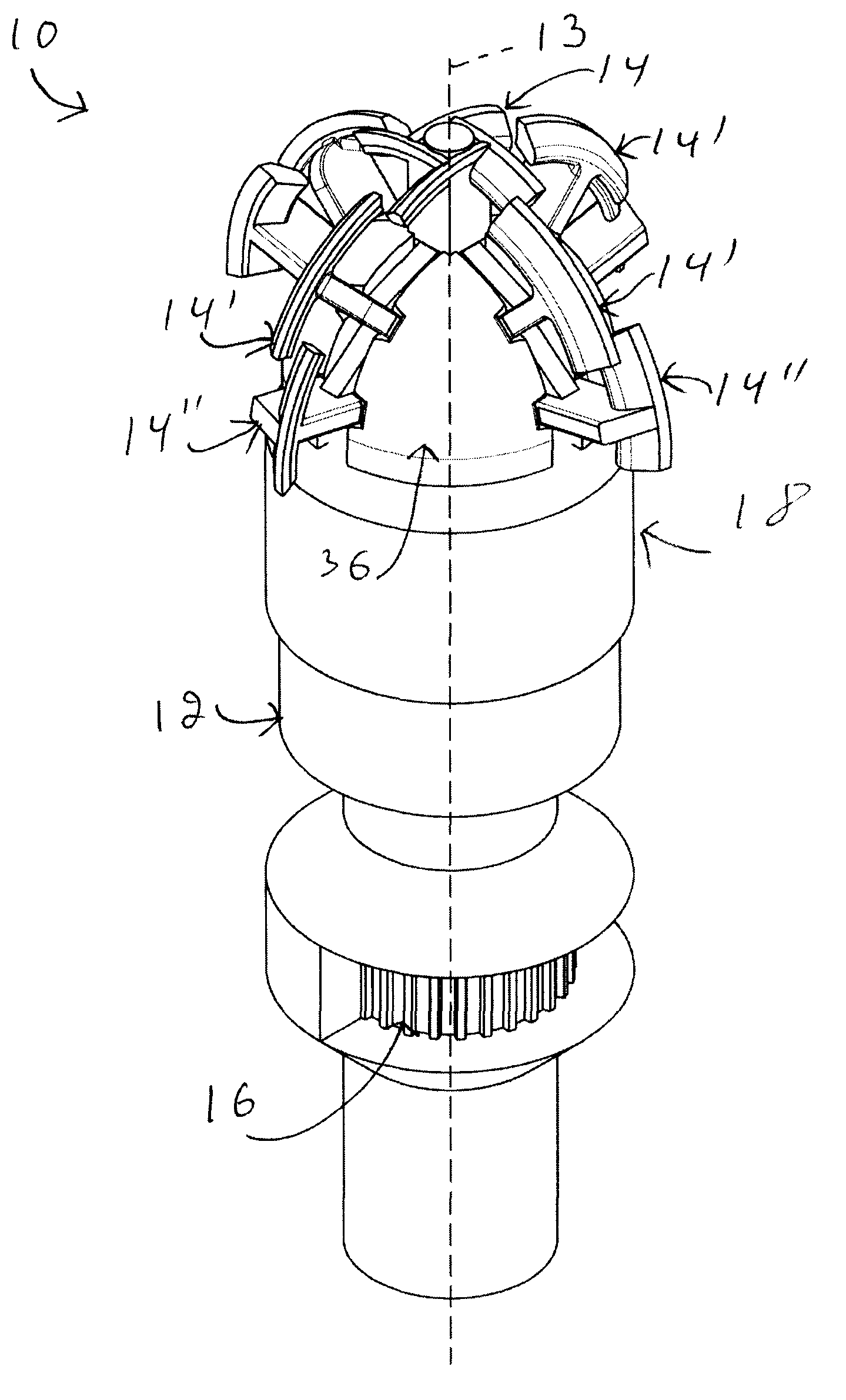
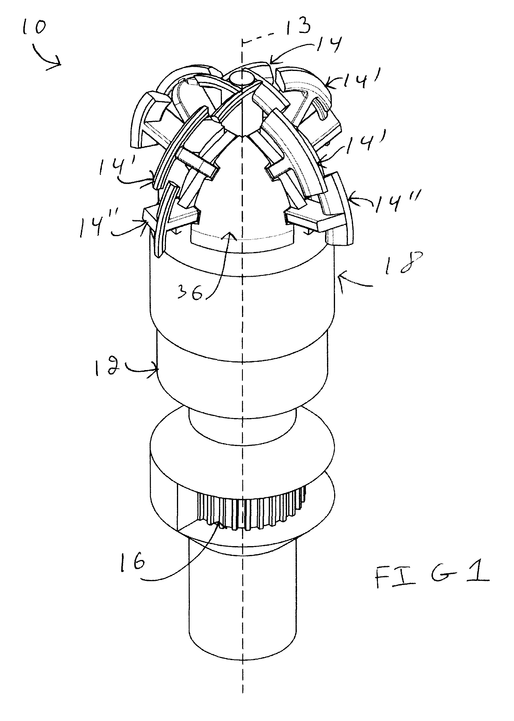
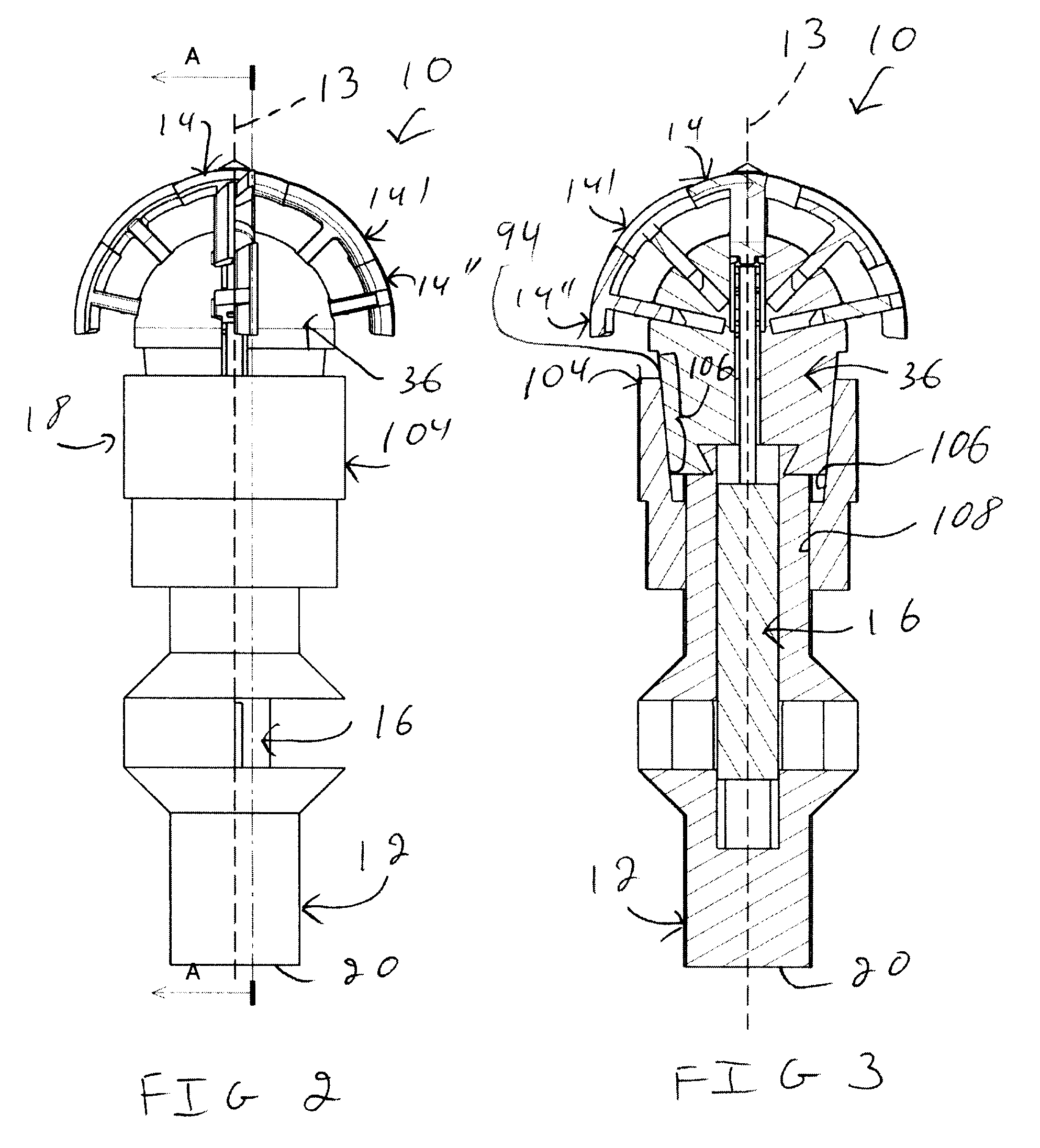
[0053]Referring to FIG. 1, there is shown an acetabular reamer 10 usable by an intended user (not shown in the drawings) for reaming an acetabulum (not shown in the drawings). The acetabular reamer 10 includes a body 12, the body 12 defining a rotation axis 13 about which the acetabular reamer 10 is rotatable by the intended user.

[0054]The acetabular reamer 10 includes at least one reaming element 14, 14′, 14″. As described in further details hereinbelow, the acetabular reamer 10 shown in the drawings includes a reaming element of a first type 14, four reaming elements of a second type 14′ and four reaming elements of a third type 14″. However, in alternative embodiments of the invention, the acetabular reamer 10 includes any suitable number of reaming elements 14, 14′ and 14″ and any suitable number of types of reaming elements 14, 14′, 14″.

[0055]Each reaming element 14, 14′14″ is operatively coupled to the body 12 so as to be movable between a respective reaming element inner posi...


PUM


Abstract

A acetabular reamer (10) for reaming an acetabulum, reaction forces being exerted onto the acetabular reamer by the acetabulum when the acetabulum is reamed, the acetabular reamer comprising: a body (12), the body (12) defining a rotation axis (13) about which the acetabular reamer (10) is rotatable; a reaming element (14, 14′, 14″) operatively coupled to the body (12) so as to be movable between a reaming element inner position and a reaming element outer position relatively thereto, the reaming element (14, 14′, 14″) being positioned further away from the rotation axis in the reaming element outer position than in the reaming element inner position; an actuator (16) operatively coupled to the reaming element (14, 14′, 14″) for moving the reaming element (14, 14′, 14″) between the reaming element inner and outer positions; and a reaming element lock (18) configurable between a locked configuration and an unlocked configuration, the reaming element lock (18) being operatively coupled to the reaming element (14, 14′, 14″) in a manner such that when the reaming element lock (18) is in the unlocked configuration, the reaming element (14, 14′, 14″) is substantially freely movable by the actuator (16) between the reaming element inner and outer positions, and when the reaming element lock (18) is in the locked configuration, the reaming element lock (18) substantially prevents the reaming element (14, 14′, 14″) from moving relatively to the body (12); the reaming element lock (18) being configured, sized and operatively coupled to the reaming element (14, 14′, 14″) and the body (12) in a manner such that when the reaming element lock (18) is in the locked configuration and the reaction forces are exerted onto the reaming element (14, 14′, 14″), a larger portion of the reaction forces is transmitted to the body (12) than to the actuator (16).

Description

FIELD OF THE INVENTION[0001]The present invention relates to the art of surgical devices. More specifically, the present invention is concerned with an acetabular reamer.BACKGROUND[0002]Acetabular reamers are used in hip replacement surgery to prepare the acetabulum of the hip of a patient before the attachment of an acetabular cup thereto. In such surgeries, there is typically a need to prepare the acetabulum so that a substantially spherical cap-shaped surface is provided to receive a substantially hemispherical acetabular cup. To that effect, a surgeon typically uses a reamer including a substantially hemispherical reaming element in which asperities are formed. The reaming element is longitudinally mounted to the distal end of an axle and the axle is attached to a rotary power tool such as, for example, a drill. The drill rotates the axle about the longitudinal axis of the axle, thereby rotating the reaming element to allow reaming of the acetabulum.[0003]Hip replacement surgery...

Claims


Application Information

Patent Timeline
Patent Type & Authority Applications(United States)
IPC IPC(8): A61B17/16
CPCA61B17/1617A61F2/34A61B17/1666
Inventor PETIT, YVANFERNANDES, JULIOMERETTE, JEAN-SEBASTIENDANSEREAU, MATHIEUSONGMENE, VICTORCARRIER, MATHIEU
Owner ECOLE DE TECH SUPERIEURE
Why Eureka
Try Eureka