Stand alone anterior cage

Inactive Publication Date: 2010-11-11
STRYKER EURO OPERATIONS HLDG LLC
View PDF21 Cites 150 Cited by
  • Summary
  • Abstract
  • Description
  • Claims
  • Application Information

AI Technical Summary

Benefits of technology

[0010]The third aspect of the present invention is a method of fusing together first and second vertebral bodies. In accordance with one embodiment of the present invention, the method includes the steps of preparing a space between the first and second vertebral bodies to a spinal implant, implanting a shell, the shell including a first plate, a second plate, and a living hinge connecting the first and second plates, placing a first screw through the first plate and into the first vertebral body, placing a second screw through the second plate and into the second vertebral body, and inserting an insert between the first and second plates, wherein the insert prevents backout of the first and second screws.
[0011]In accordance with other embodiments of this third aspect, the inserting step may cause the first and second plates to move with respect to each other and s

Problems solved by technology

The deterioration of vertebral bodies and/or vertebral discs is a major cause of back and neck pain in many patients.
Nonetheless, even given the success of such motion preserving devices, it is still sometimes necessary to fuse adjacent vertebral

Method used


Image

  • Stand alone anterior cage
  • Stand alone anterior cage
  • Stand alone anterior cage

Examples


Embodiment Construction

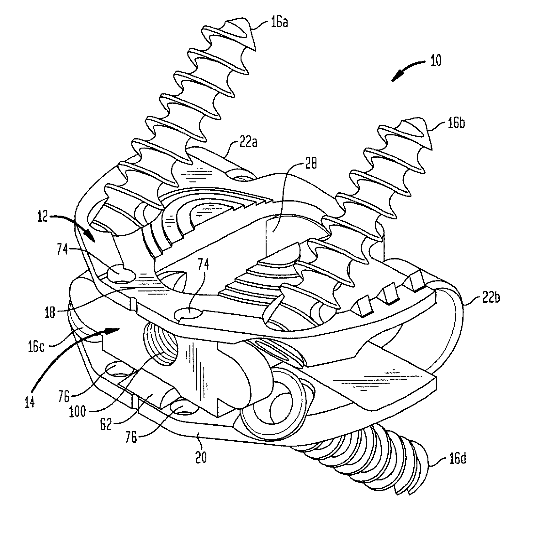
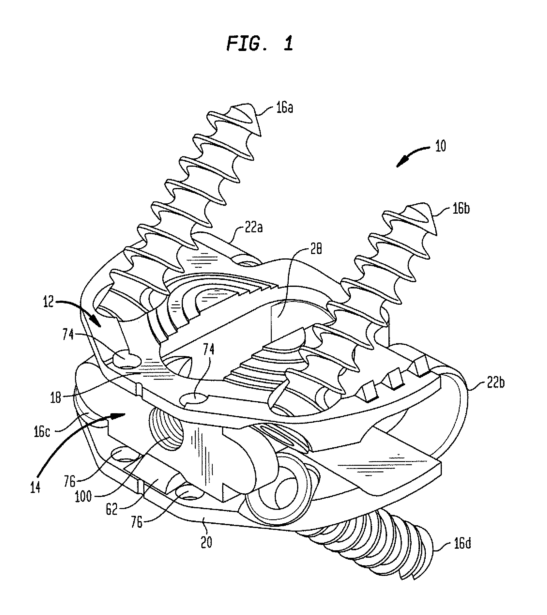
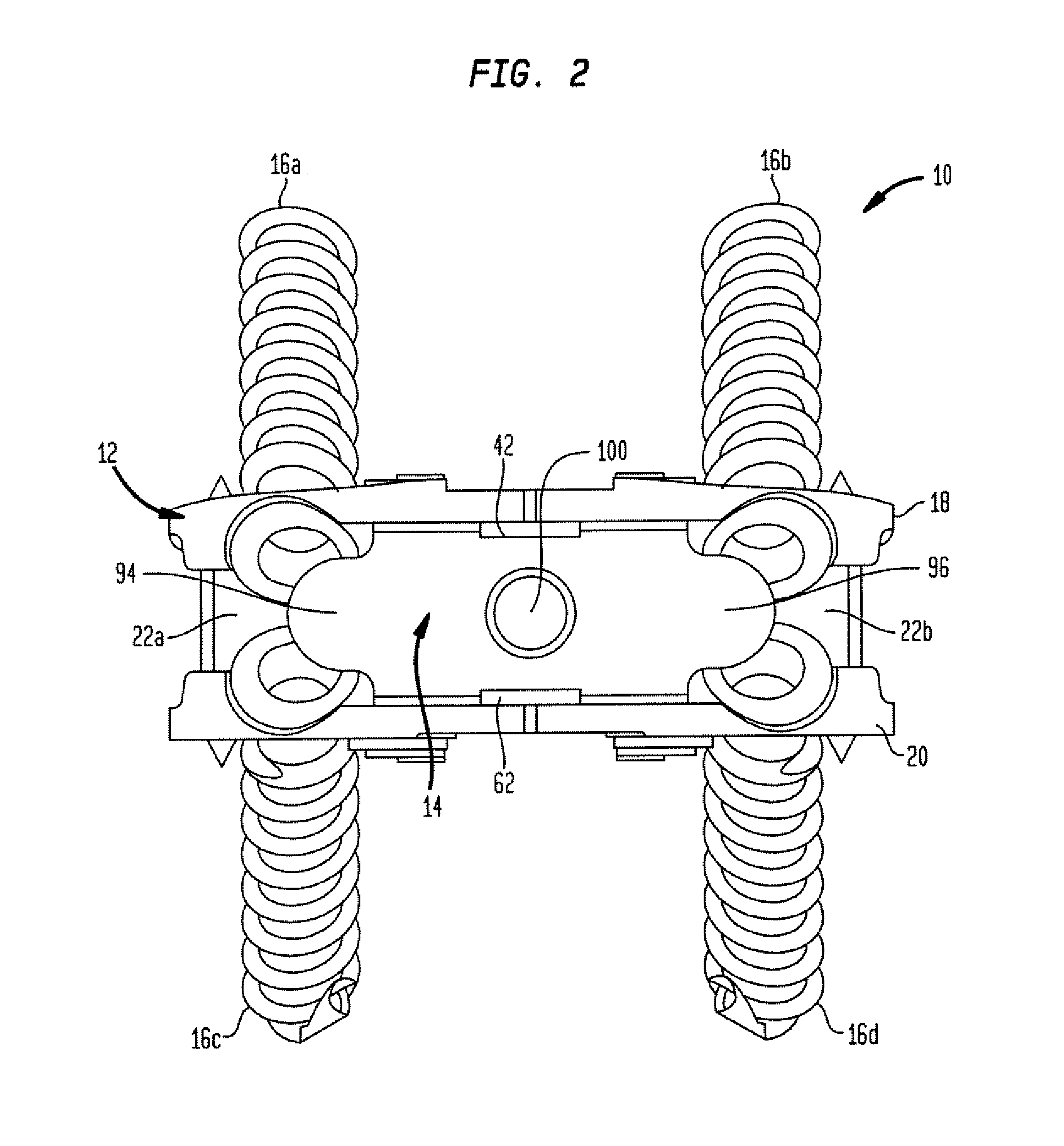
[0032]Referring to the drawings, wherein like reference numerals refer to like elements, FIGS. 1-6 depict a first embodiment intervertebral fusion device or spinal implant for fusing together first and second vertebral bodies, designated generally by reference numeral 10. As is shown in the drawings, implant 10 includes a shell 12 and an insert 14. Moreover, implant 10 is also provided with a plurality of fasteners (shown in the drawings as screws 16a-d) for placement through portions of the shell and into adjacent vertebral bodies. However, one of ordinary skill in the art would readily recognize that other types of fasteners could be utilized, e.g., pins or the like. The specifics of each of the components of implant 10, as well as their operation and use will be discussed more fully below.

[0033]As is shown in FIGS. 1-6 and even more specifically shown in FIGS. 7-9, shell 12 includes a first plate or member 18, a second plate or member 20, and a pair of resilient or living hinge m...


PUM


Abstract

The present invention teaches an improved spinal fusion implant and method of implanting same. The implant includes a shell and an insert, the insert capable of situating first and second plates of the shell with respect to each other and of preventing unwanted loosening of fasteners placed through the shell and into the adjacent vertebral bodies. The method includes implanting a shell, selecting an insert from a plurality of inserts, and placing an insert between first and second plates of the shell.

Description

BACKGROUND OF THE INVENTION[0001]The present invention is directed to spinal implants, and more particularly, spinal fusion implants.[0002]The deterioration of vertebral bodies and / or vertebral discs is a major cause of back and neck pain in many patients. Through the years, many different techniques for restoring the natural anatomical spacing in the spine and thereby alleviating this pain have been developed and practiced by surgeons. For instance, implants and techniques for implanting such implants have been designed to preserve motion between adjacent vertebral bodies. These motion preserving implants are adapted to emulate a removed spinal disc. Examples of such implants (and the methods of implanting same) are disclosed in U.S. Pat. Nos. 6,989,032 (“the '032 patent”) and 7,169,182 (“the '182 patent”), the disclosures of which are hereby incorporated by reference herein. Nonetheless, even given the success of such motion preserving devices, it is still sometimes necessary to f...

Claims


Application Information

Patent Timeline
IPC IPC(8): A61F2/44A61B17/70A61B17/88
CPCA61F2/442A61F2310/00023A61F2002/30504A61F2002/30571A61F2002/30596A61F2002/30598A61F2002/30616A61F2002/30626A61F2002/30632A61F2002/30736A61F2002/30787A61F2002/30843A61F2002/30848A61F2002/4475A61F2002/4629A61F2220/0025A61F2310/00017A61F2/4455A61B17/8042A61F2002/305A61F2002/30593A61F2002/30594A61F2002/30624A61F2002/30845
Inventor ERRICO, THOMAS J.DE MOURA, ALEXANDRE B.MCDONNELL, CHRISTOPHERZUBOK, RAFAIL
Owner STRYKER EURO OPERATIONS HLDG LLC
Why Eureka
Try Eureka