Filament Clamp for a Vegetation Trimmer

a technology of vegetation trimmer and filament clamp, which is applied in the field of spools, can solve the problems of shortened life span of the trimmer, more filament to be paid out from the spool, and tangle of filament, and achieve the effect of significantly reducing the amount of time needed to cut an area of vegetation

Inactive Publication Date: 2010-11-18
DOANE IAN J +1
View PDF25 Cites 11 Cited by
  • Summary
  • Abstract
  • Description
  • Claims
  • Application Information

AI Technical Summary

Benefits of technology

[0010]An object of this invention is to create a trimmer head and spool assembly in which the filament does not tangle or weld together. The amount of time that is necessary to cut an area of vegetation is significantly reduced because the operator does not need to disassemble and reassemble the hub and spool assembly except to add new filament when the old filament supply is exhausted.
[0011]Another object of the invention is to create a trimmer head and spool assembly in which the user can operate in a manner similar to that of the bump feed trimmers that are in common use. The clamp function works in conjunction with the bump feed system so the user does not have to activate the clamp by any means. Also, the clamp function works regardless of how the user winds the filament around the spool. This eliminates the need for special spool winding systems or the need to purchase pre-wound spools.

Problems solved by technology

A common problem associated with this arrangement is that the force that is generated by the filament in the cutting plane is allowed to act on the filament wound around the spool, thus causing the filament to tangle and this does not permit more filament to pay out from the spool.
The main drawback is that the operator has to stop the trimmer motor in order to refresh the filament multiple times as he is operating the trimmer, thus leading to a shortened life span of the trimmer due to constant starting and stopping of the motor and more time is required to trim an area of vegetation.
A common practice is to use an extended length of filament in order to increase the amount of vegetation that can be cut without having to refresh the filament, but this poses a serious safety hazard.
However, the cost of the pre-wound spool is significantly greater than the filament itself.
The extra mechanism is more expensive to use rather than if the user was able to wind the filament himself.

Method used


Image

  • Filament Clamp for a Vegetation Trimmer
  • Filament Clamp for a Vegetation Trimmer
  • Filament Clamp for a Vegetation Trimmer

Examples


Embodiment Construction

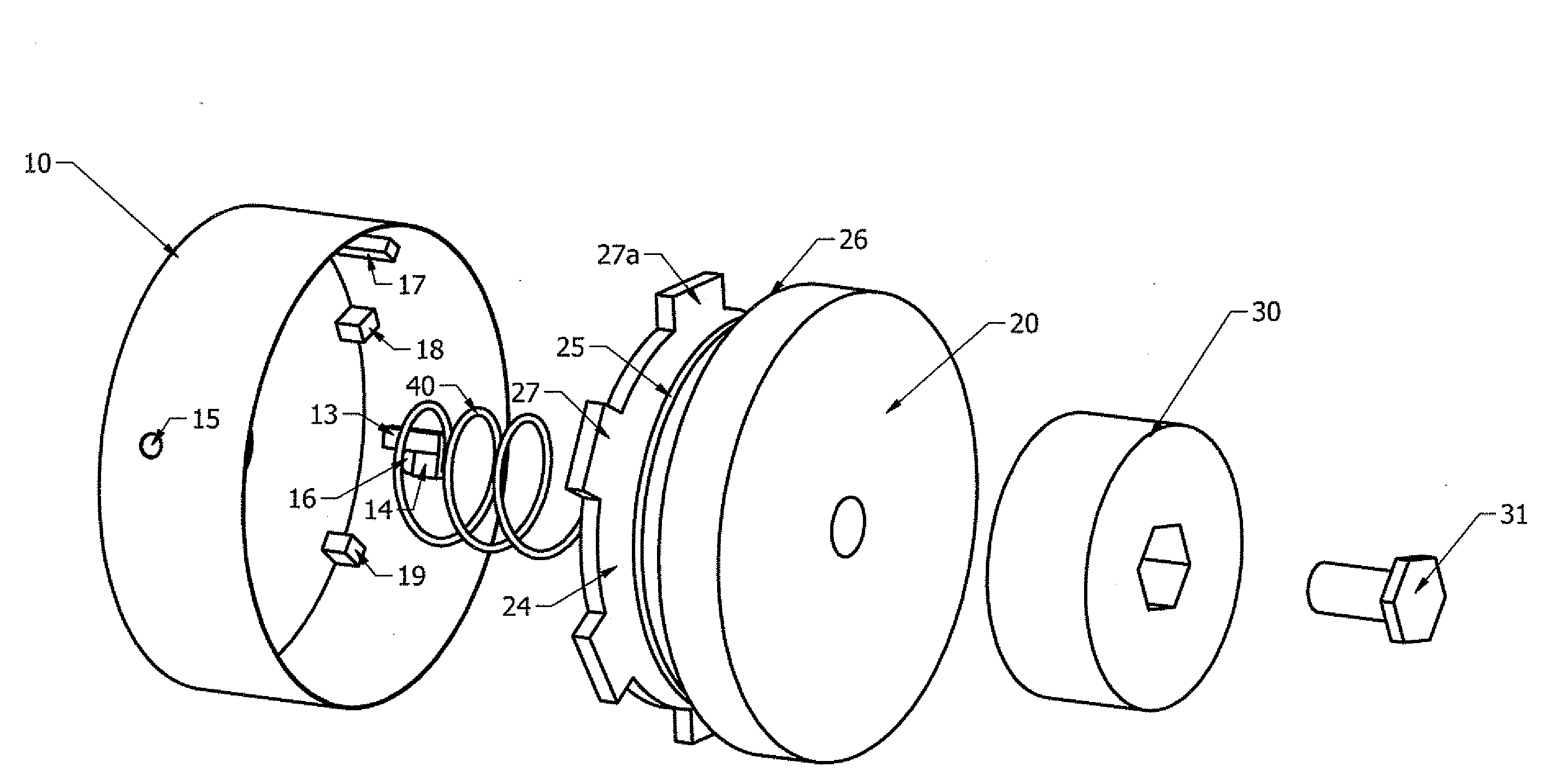
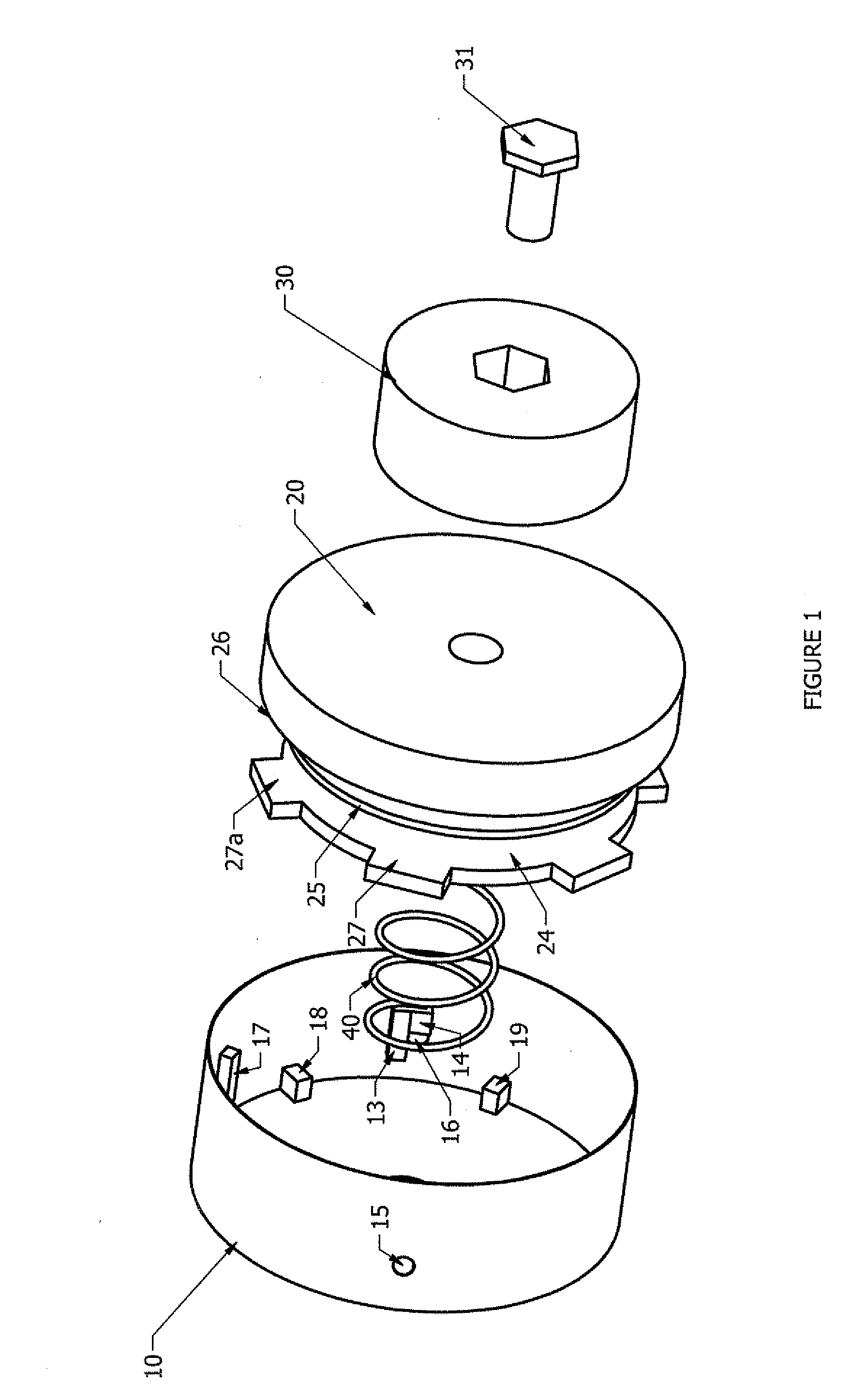
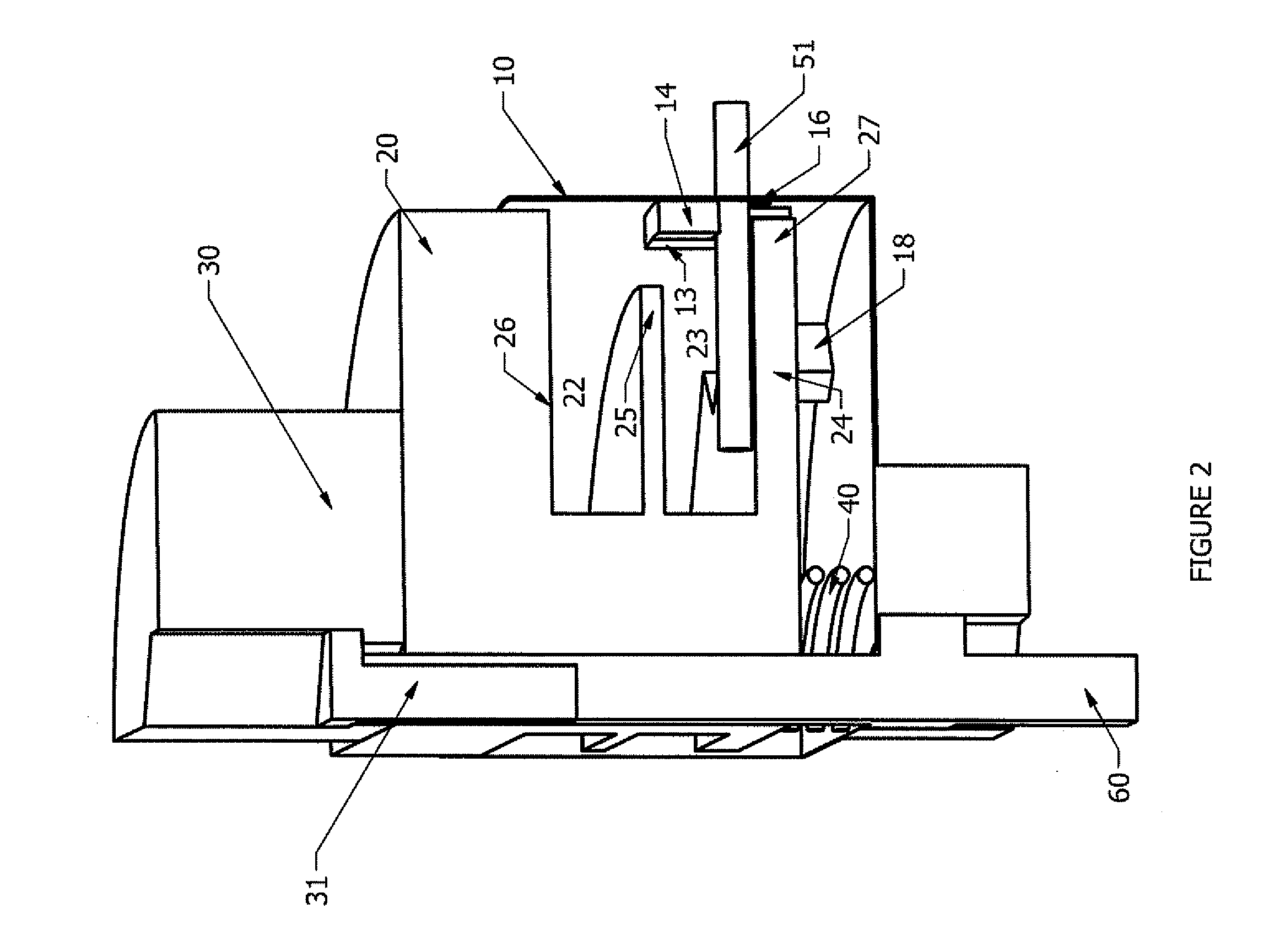
[0018]Referring to FIGS. 1 and 2, hub 10 is rotationally locked to shaft 60. Filament 51 is wound around spool 20 in cavity 23. Cavity 23 is created by walls 24 and 25. When assembled, filament 51 extends through aperture 16 see FIG. 1. When spool 20 is in second position, arm 18 engages momentarily with arm 27 to regulate the amount of relative rotation between hub 10 and spool 20 and also causes spool 20 to enter into first position. Bolt 31 threads into shaft 60 to contain the entire assembly.

[0019]Referring now to FIG. 2, arm 13 rotationally locks arm 27 to prevent relative rotation between spool 20 and hub 10. Biasing member 40 normally biases arm 27 against arm 14 to forcibly clamp filament 51. When bumper sub 30 is struck against a hard surface, spool 20 enters into second position.

[0020]Referring now to FIG. 3, arm 27 is disengaged from arm 13. This allows spool 20 to rotate relative to hub 10 to allow filament 51 to unwind from spool 20. Further, arm 27 is separated from ar...


PUM


Abstract

A vegetation trimmer with a spool and hub assembly has a cutting filament wound around the spool. The free end of the filament extends through an aperture in the hub into the cutting plane. The spool and hub are rotated at a high rate to allow the filament to cut vegetation. The spool includes a plurality of arms which engage with arms on the hub. When the spool is acted upon, the arms on the spool disengage with the arms on the hub to permit relative rotation of the spool to the hub to feed additional filament into the cutting plane. An indexing feature is used to regulate the amount of additional cutting filament that is allowed to be fed into the cutting plane. When the spool and hub are engaged, the cutting filament is forcible clamped between the arms on the spool and the arms on the hub to prevent the centrifugal force generated by the filament in the cutting plane from acting upon the filament wound around the spool at cutting speed so that the filament does not have means to tangle or weld together and break prematurely. Upon disengagement of the spool and hub, the cutting filament is released to permit the additional cutting filament to be fed into the cutting plane.

Description

FIELD OF THE INVENTION[0001]The present invention relates generally to line trimmers for cutting vegetation and, more particularly, relates to spools having filament wound thereon which are installed the hubs of trimmers.BACKGROUND OF THE INVENTION[0002]Vegetation trimmers are in common use to cut grass in areas that a mower typically does not reach such as along walkways, fences, and houses. Most trimmers comprise of a filament that is wound around a spool. When the spool is spinning at a high rate, the filament cuts vegetation. A common problem associated with this arrangement is that the force that is generated by the filament in the cutting plane is allowed to act on the filament wound around the spool, thus causing the filament to tangle and this does not permit more filament to pay out from the spool. The operator has to stop the trimmer and disassemble the hub and spool assembly to untangle the filament.[0003]Fixed line trimmers have been developed to completely remove the pr...

Claims


Application Information

Patent Timeline
Patent Type & Authority Applications(United States)
IPC IPC(8): A01D34/416
CPCA01D34/416A01D34/4161
Inventor DOANE, IAN J.DOANE, JAMES C.
Owner DOANE IAN J
Why Eureka
Try Eureka