Jet engine shield and debris deflector

a technology of debris deflector and jet engine, which is applied in the direction of machines/engines, mechanical equipment, transportation and packaging, etc., can solve the problems of more problems for larger birds, and achieve the effects of saving fuel, improving safety, and adding to the beauty of aircra

Inactive Publication Date: 2010-11-18
CUNNINGHAM RAY E
View PDF3 Cites 18 Cited by
  • Summary
  • Abstract
  • Description
  • Claims
  • Application Information

AI Technical Summary

Benefits of technology

[0021]The shield structure attaches to the air intake portion of the jet engine and is designed to be an attractive ornamentation adding to the beauty of the aircraft. The device is aerodynamically shaped in the form of a solid frustro-conical cylinder having an open, proximate end sized to fit the cowling of the jet engine intake and a closed distal end pointed in the direction of the aircraft during a normal flight pattern. The shape is designed to act as a deflector of any material impacting against the shield with the exception of a direct hit.
[0022]The shield device is formed using aircraft grade aluminum of substantial thickness in order to withstand impacts from large objects. The shield is formed with a series of openings or slots that allow sufficient air to be entrained into the jet engine intake. The orientation and shape of the slots direct the air directly to the turbine blades so that the engine operates efficiently thus saving fuel during normal flight conditions.
[0023]In a preferred embodiment, the openings are a series of elongated slots extending from the closed front end of the shield device to the rear proximate end adjacent the attachment to the air intake cowling of the jet engine. In this embodiment the slots are equally sized and are located in a general parallel arrangement. The slots flare outwardly toward the jet engine. The land areas of the shield body between the slots are wider than the slots. This structure creates increased integrity and strength of the shield in order that it may withstand a substantial impact without deforming. The slots may be provided with additional air directing surfaces to more efficiently deliver the intake air to the engine.

Problems solved by technology

Larger birds become more of a problem.

Method used


Image

  • Jet engine shield and debris deflector
  • Jet engine shield and debris deflector
  • Jet engine shield and debris deflector

Examples


Embodiment Construction

FIGS. 1 to 5—Preferred Embodiment

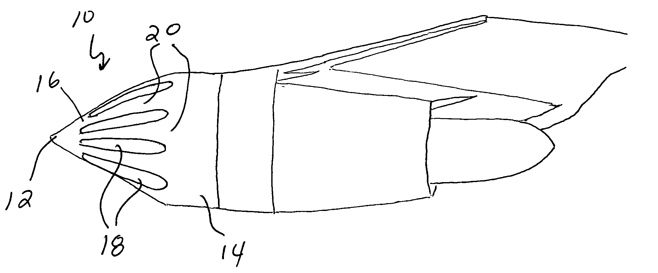
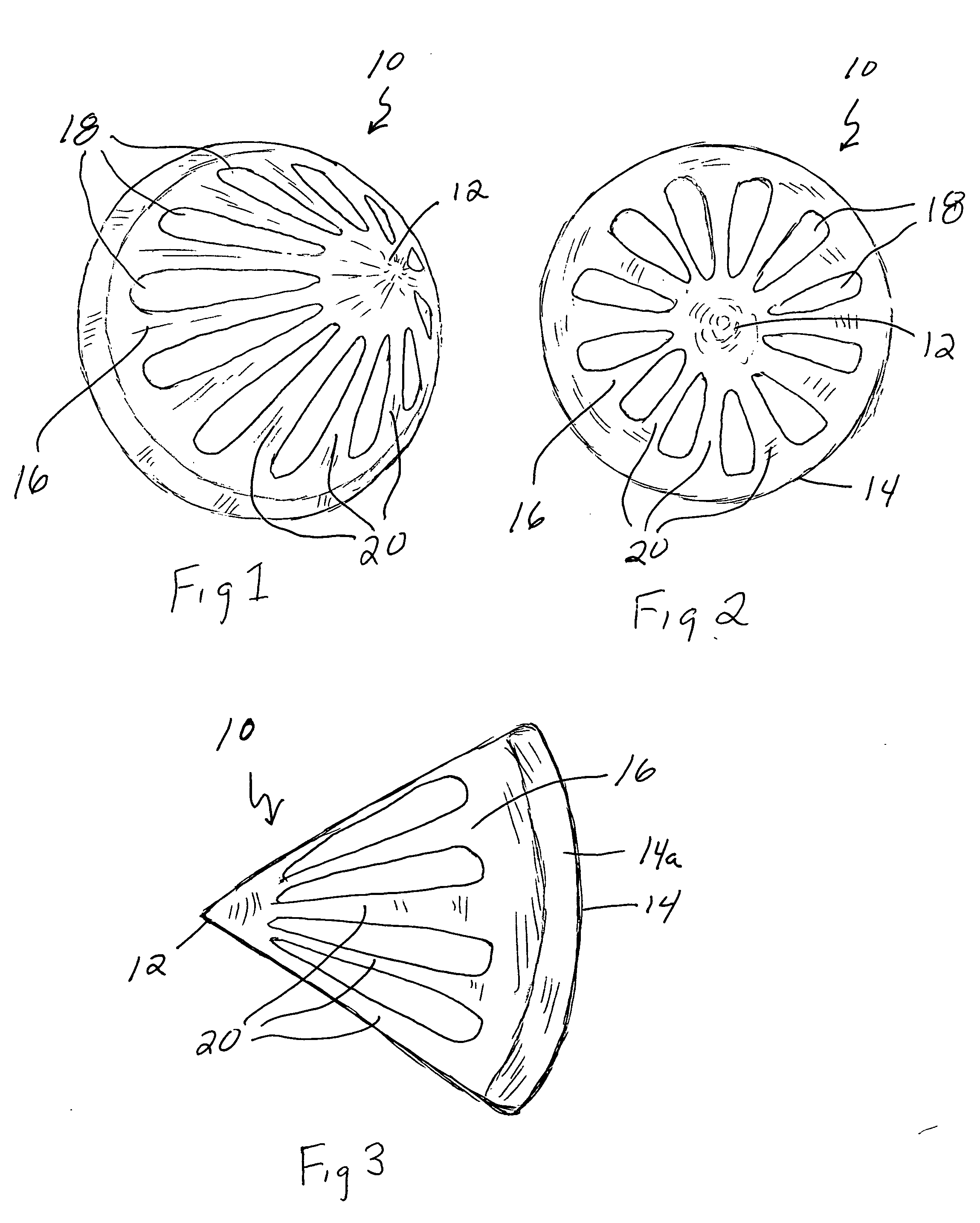
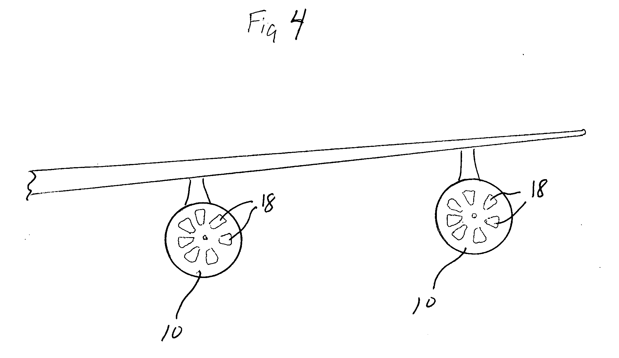
[0034]Referring to the drawings, FIGS. 1 to 5 illustrate a first embodiment of jet engine air intake shield 10 of the present invention. The shield 10 is formed of aircraft strength aluminum with a frustro-conical, aerodynamic shape. The forward or distal end 12 is closed and forms a generally pointed surface in the direction that an aircraft will travel during normal flight. The rear or proximate end 14 is open and shaped to conform to the air opening of a jet engine. In this embodiment, the end 14 is flattened into a cylindrical shape to facilitate connection to a majority of jet engine shapes. The body 16 of the shield 10 between the closed forward end 12 and the open rear end 14 has a smooth shape that presents minimum air resistance when mounted on the front of a jet engine.

[0035]The shield 10 is formed with a series of elongated air slots 18 in a front to rear direction on the body 16 of the shield 10 between the forward end 12 and the rear end...


PUM


Abstract

A jet engine bird and debris shield device is disclosed that is designed as a deflector to deflect large birds, such as geese weighing in excess of eight pounds, and keep from entering the turbine blades of a jet engine. The shield device is aerodynamically shaped in the form of a frustro-conical cylinder aligned to the direction of flight and attaches to the air intake portion of the jet engine. The shield is formed with a series of openings or slots that allow sufficient air to be entrained into the jet engine intake. The orientation and shape of the slots direct the air directly to the turbine blades of the engine.

Description

CROSS REFERENCE TO RELATED APPLICATIONS [0001]Not ApplicableBACKGROUND[0002]1. Field of Invention[0003]The present invention relates to aircraft safety and in particular to a jet engine shield and debris deflector.FEDERALLY SPONSORED RESEARCH [0004]Not ApplicableSEQUENCE LISTING OR PROGRAM [0005]Not Applicable[0006]2. Prior Art[0007]It is a fairly common occurrence for jet aircraft to be struck by flying debris resulting in serious damage; particularly should this material be ingested into the air intake of a jet engine. This most often occurs when a large bird, such as a large goose, or flock of birds are encountered in the flight path of the aircraft. In the past 20 years it is estimated that there have been between 80,000 and 100,000 bird collisions with aircraft. The resulting damage from these collisions can disable the engine causing the aircraft to be forced to attempt to make an emergency landing resulting in, or in a worse case scenario, causing the aircraft to crash. In ad...

Claims


Application Information

Patent Timeline
Patent Type & Authority Applications(United States)
IPC IPC(8): F02G3/00
CPCB64D33/02F02C7/055B64D2033/022
Inventor CUNNINGHAM, RAY E.
Owner CUNNINGHAM RAY E
Why Eureka
Try Eureka