Source driver and driving method thereof

a source driver and driver technology, applied in the field of source drivers, can solve the problems of hurting human eyes, requiring more and more rapid refreshing of scan lines, and contradicting power saving designs, so as to save power consumption and reduce the operation temperature of source drivers

Active Publication Date: 2010-11-18
HIMAX TECH LTD
View PDF9 Cites 23 Cited by
  • Summary
  • Abstract
  • Description
  • Claims
  • Application Information

AI Technical Summary

Benefits of technology

[0009]Accordingly, the present invention is directed to provide a source driver, capable of controlling a charging sharing function thereof in a display to save the power consumption and to lower the operation temperature of the source driver.

Problems solved by technology

Despite of advantages it may have, a conventional cathode-ray tube (CRT) display not only is large in bulk that occupies too much room because of its intrinsic structure of the electronic cavity, but also radiates rays which may hurt human eyes.
Consequently, refreshing frequencies of scan lines are demanded to be more and more rapid, which contradicts the designs for power saving by system engineers.
Therefore, such charge sharing technology is not suitable for the specific condition mentioned above.
Because the swings of the voltages are much than desire, extra power is consumed.

Method used


Image

  • Source driver and driving method thereof
  • Source driver and driving method thereof
  • Source driver and driving method thereof

Examples


Embodiment Construction

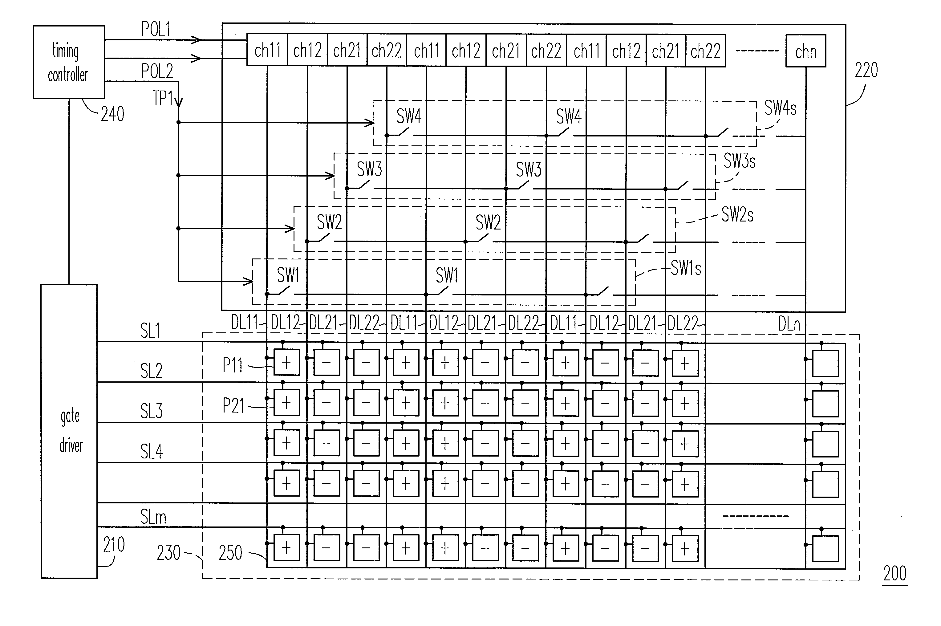
[0023]FIG. 2 is a block diagram for a circuit of a display 200 according to an embodiment of the invention. Referring to FIG. 2, the display 200 includes a gate driver 210, a source driver 220, a display panel 230, and a timing controller 240, wherein the display panel 230 includes a pixel array 250, and the timing controller 240 controls the source driver 220 and the gate driver 210.

[0024]The source driver 220 includes a plurality of first data channel pairs, a plurality of second data channel pairs, a first switch group SW1s, a second switch group SW2s, a third switch group SW3s, and a fourth switch group SW4s. In the present embodiment, a first odd channel ch1 and a neighboring first even channel ch12 form one of the first data channel pairs. Similarly, a second odd channel ch21 and a neighboring second even channel ch22 form one of the second data channel pairs. Besides, the first switch group SW1s and the second switch group SW2s are coupled to the first data channel pairs, and...


PUM


Abstract

A source driver includes a plurality of first data channel pairs, a plurality of second data channel pairs, a first switch group, a second switch group, a third switch group, and a fourth switch group. Each of the first data channel pairs includes a first odd channel and a first even channel. The channels outputting voltages having the same polarity are short circuited together through the switch groups during a charge sharing period. As a result, the swings of the voltages of data lines coupled the corresponding channel are reduced, and further power consumption in the source driver could be reduced as compared with the related art.

Description

BACKGROUND OF THE INVENTION[0001]1. Field of the Invention[0002]The present invention relates to a source driver. More particularly, the present invention relates to a source driver for reducing power consumption thereof with a charge sharing function, and a driving method thereof.[0003]2. Description of Related Art[0004]In order to catch up with the modern lifestyle, video and image devices are becoming slimmer and lighter. Despite of advantages it may have, a conventional cathode-ray tube (CRT) display not only is large in bulk that occupies too much room because of its intrinsic structure of the electronic cavity, but also radiates rays which may hurt human eyes. Therefore, accompanying the development of optoelectronic technology and semi-conductor processing technology, flat panel displays including liquid crystal display (LCD), organic light-emitting diode (OLED) display and plasma display panel (PDP) are gradually becoming a mainstream in the display market.[0005]Resolutions ...

Claims


Application Information

Patent Timeline
Patent Type & Authority Applications(United States)
IPC IPC(8): G09G5/00G06F3/038
CPCG09G3/3614G09G3/3688G09G2330/023G09G2330/021G09G2310/0248
Inventor WENG, MENG-TSE
Owner HIMAX TECH LTD
Why Eureka
Try Eureka