Recording material delivery system for recording material-consuming apparatus; circuit board; structural body; and ink cartridge
a material delivery system and material-consuming technology, applied in the direction of electrographic process apparatus, instruments, printing, etc., can solve problems such as malfunction or disabling of memory devices, and achieve the effects of reducing the probability of detection errors relating to installation status in the recording material-consuming apparatus, reducing the likelihood of problems that may arise when using electrical connections that rely on terminals, and reducing the probability of problems that may arise when using electrical connections. relying on terminals
- Summary
- Abstract
- Description
- Claims
- Application Information
AI Technical Summary
Benefits of technology
Problems solved by technology
Method used
Image
Examples
embodiment 1
A. Embodiment 1
A1. Apparatus Configuration:
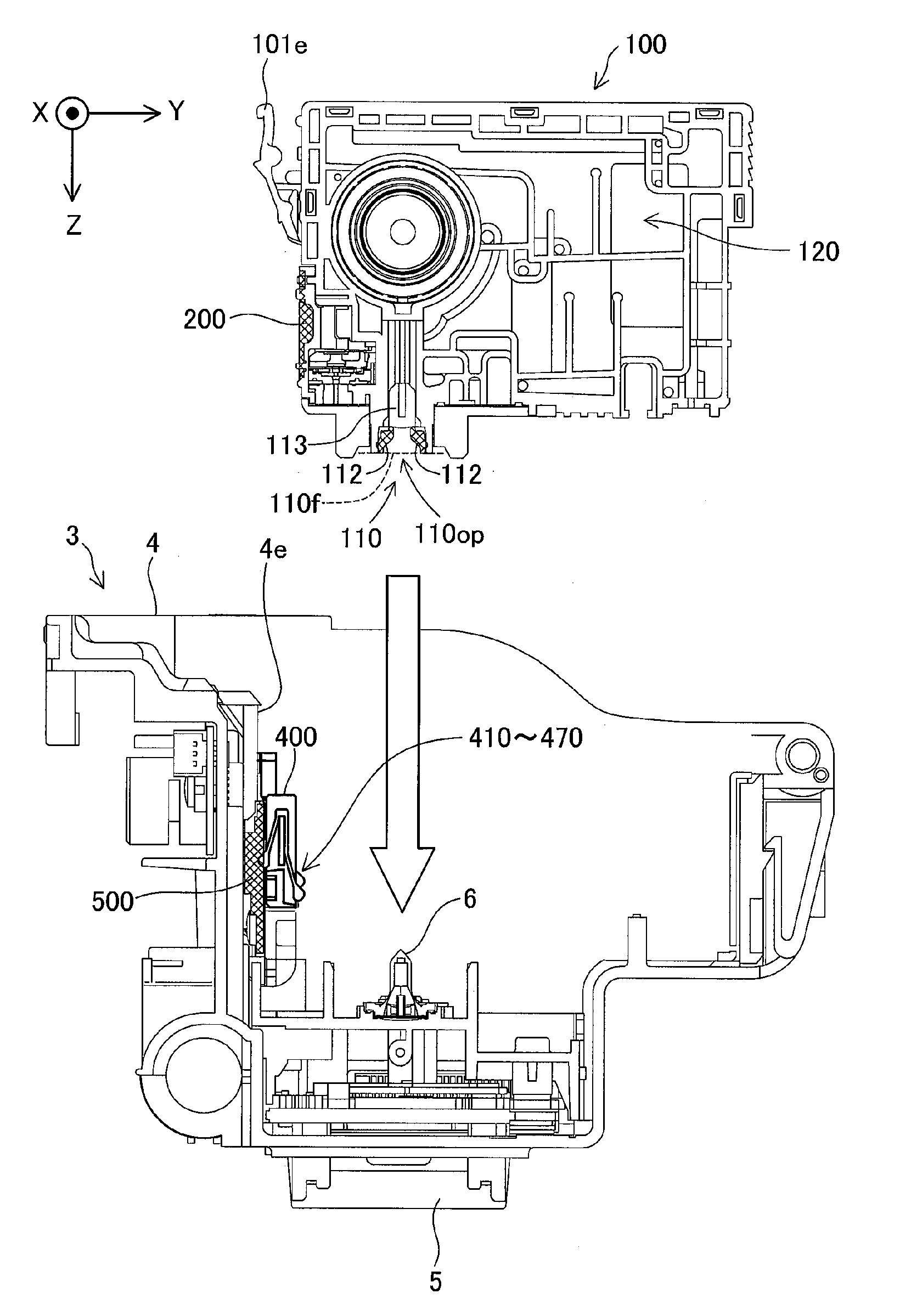
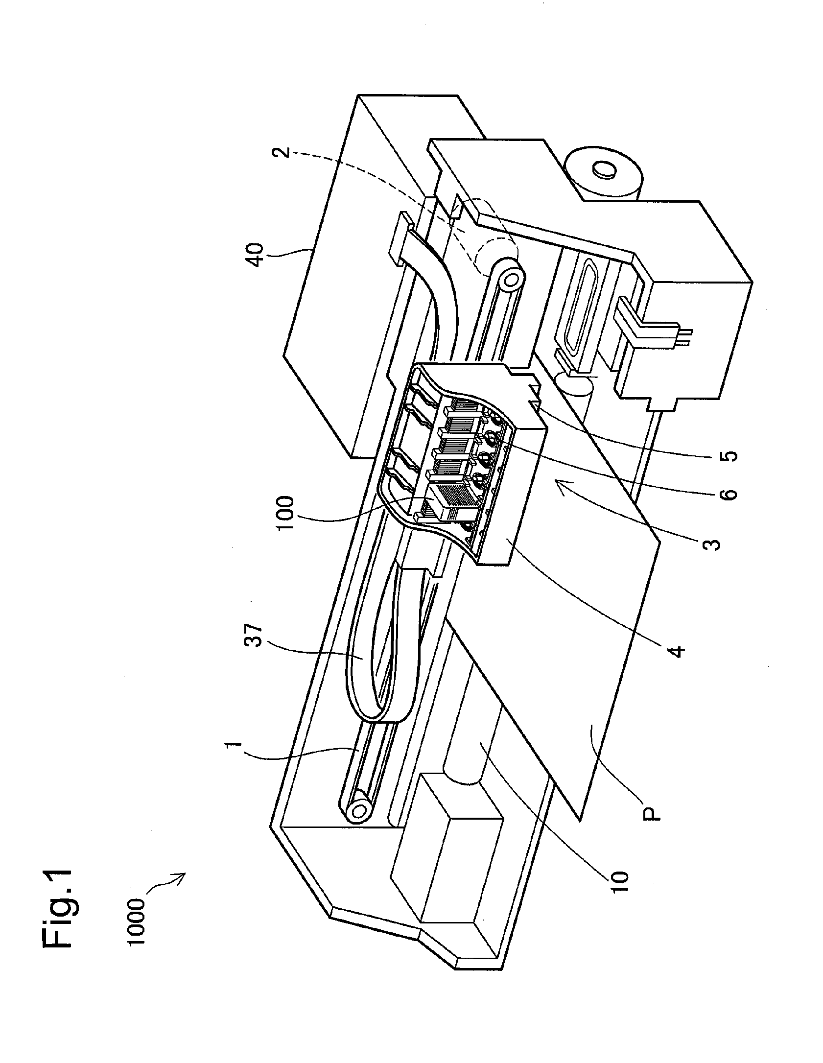
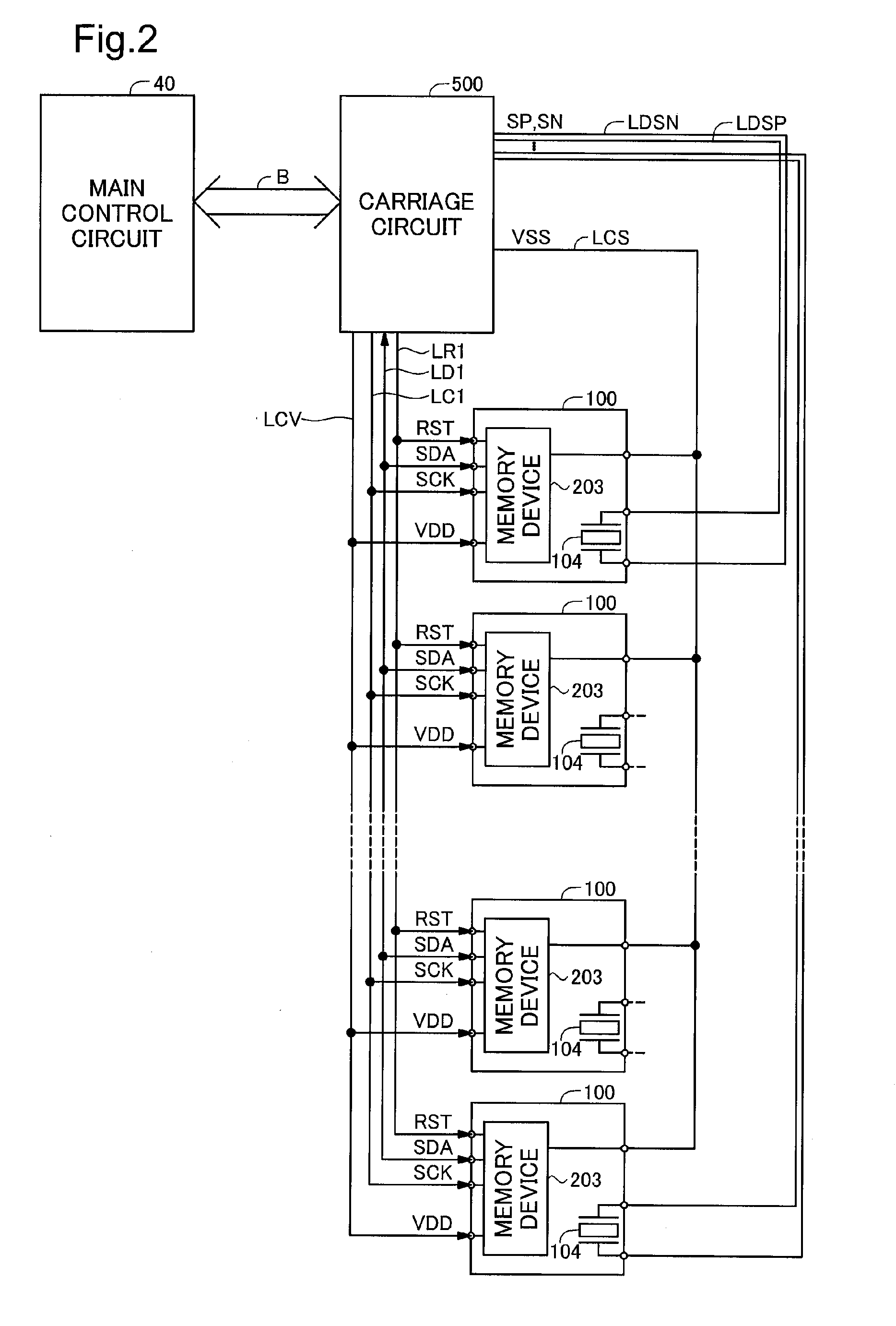
[0079]FIG. 1 is an illustration depicting a printer according to an embodiment of the present invention. The printer is one example of a recording material-consuming apparatus. A recording material-consuming apparatus consumes a recording material in the course of carrying out recording. The printer 1000 has a sub-scan feed mechanism, a main scan feed mechanism, and a head driving mechanism. The sub-scan feed mechanism includes a paper feed motor (not shown) and a paper feed roller 10 that is driven by the paper feed motor. The sub-scan feed mechanism is adapted to convey a sheet of printer paper P in the sub-scanning direction using the paper feed roller 10. The main scan feed mechanism is adapted to use the power of a carriage motor 2 to produce reciprocating motion in the main scanning direction by a carriage 3 which is connected to a drive belt 1. The carriage 3 includes a holder 4 and a print head 5. The head driving mechanism is adapt...
embodiment 2
C. Embodiment 2
[0171]FIGS. 22 and 23 are perspective views showing a second embodiment of the ink delivery system (recording material delivery system). It differs from the embodiment depicted in FIGS. 6A and 6B only in that, of the elements of the ink cartridge 100, the ink receptacle 130 (the ink delivery port 110 and the ink chamber 120 in their entirety) is separate from the other elements. The configuration of the printer 1000 is the same as the configuration of Embodiment 1 discussed previously.
[0172]This ink delivery system SI includes a structural body 100A (hereinafter also called “adaptor 100A”) and an ink receptacle portion 100B. The ink receptacle portion 100B includes a housing 101B for holding ink, and an ink delivery port 110. An ink chamber 120B for holding the ink is formed in the interior of the housing 101B. The ink delivery port 110 is formed in the base wall 101Bwb (+Z direction wall) of the housing 101B. The ink delivery port 110 communicates with the ink chambe...
embodiment 3
D. Embodiment 3
[0181]FIGS. 25 and 26 are perspective views showing a third embodiment of the ink delivery system (recording material delivery system). The principal difference from the embodiment depicted in FIGS. 22 and 23 is that the X direction wall (the wall perpendicular to the X direction) of the adaptor 100Aa (structural body 100Aa) is eliminated. The main unit 101Aa of the adaptor 100Aa has a front wall 101Aawf, a base wall 101Aawb, and a back wall 101Aawbk. The other features of the ink delivery system SIa are similar to the features of the ink delivery system SI depicted in FIGS. 22 and 23. In FIGS. 25 and 26, elements that are identical to elements in the ink delivery system SI (FIGS. 22, 23) are assigned like symbols. The circuit board 200 is secured to the front wall 101Aawf.
[0182]On the inside face of the front wall 101Aawf (the face lying towards the ink receptacle portion 100Ba) of the adaptor 100Aa there is disposed a first rail RL1 extending parallel to the install...
PUM
 Abstract
Description
Claims
Application Information
 - R&D
- Intellectual Property
- Life Sciences
- Materials
- Tech Scout
- Unparalleled Data Quality
- Higher Quality Content
- 60% Fewer Hallucinations
Browse by: Latest US Patents, China's latest patents, Technical Efficacy Thesaurus, Application Domain, Technology Topic, Popular Technical Reports.
© 2025 PatSnap. All rights reserved.Legal|Privacy policy|Modern Slavery Act Transparency Statement|Sitemap|About US| Contact US: help@patsnap.com


