Systems and Methods for Illumination and Observation

a technology of system and method, applied in the field of apparatus and methods for illumination, observation, surveillance, and tracking of objects, to achieve the effects of reducing system complexity, cost and operational logistics, and reducing system packaging

Inactive Publication Date: 2015-12-10
KAREM AIRCRAFT INC
View PDF6 Cites 6 Cited by
  • Summary
  • Abstract
  • Description
  • Claims
  • Application Information

AI Technical Summary

Benefits of technology

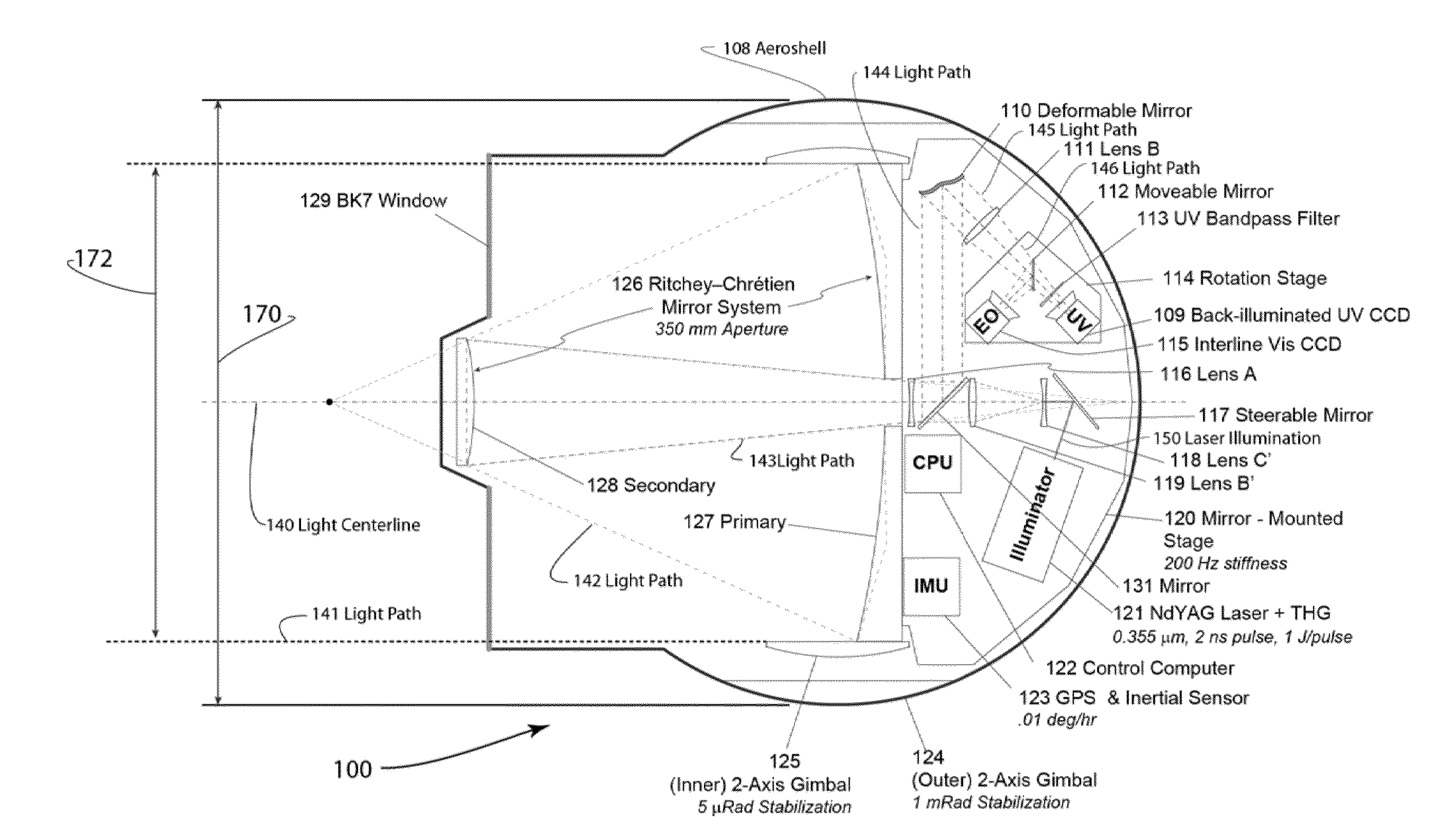
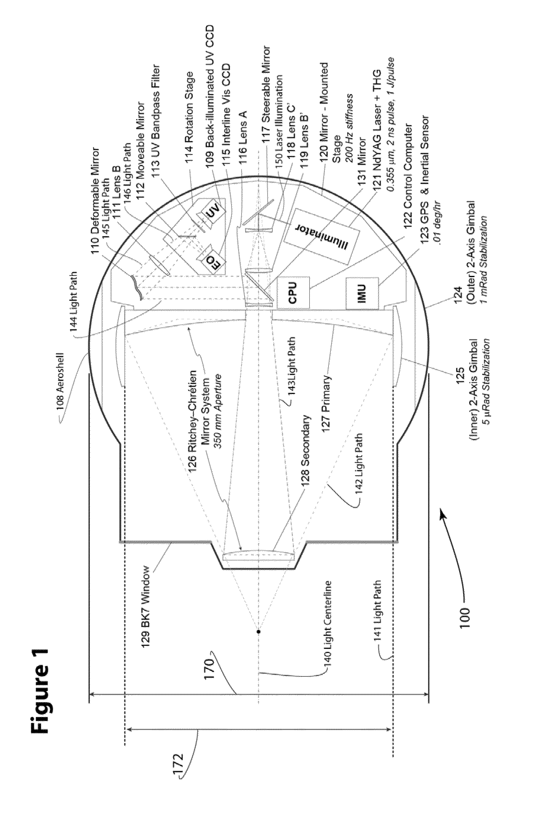
[0017]In contrast to prior art gimbal-stabilized ISR imaging systems installed on aircraft and other aerial platforms, preferred systems provide a common sensor for both day and night observation than can reduce system complexity, cost, and operational logistics. With the present system, ultraviolet light can be used for imaging during the day from a remote platform. Further, it is contemplated that the short-wavelength ultraviolet light used by preferred systems gives a higher resolution per aperture size than visible or infrared sensors, which can enable smaller system packaging and a lower cost for a given resolution requirement. Still further, it is contemplated that short-duration, high-intensity pulse and narrow-band filtering on receiver can advantageously provide noise rejection and reduced motion blur, lowering the performance requirements of the stabilizing gimbal. In preferred systems, the duration of an illuminating pulse is advantageously selected to be shorter than the light round-trip transit time, so the system can use a single set of common optics for both control of the illumination beam and focusing the returned image. This can enable a smaller size and lower cost of an ISR system for a given resolution. Finally, because the UV radiation employed by preferred systems is undetectable by the human eye and most commonly-available electronic cameras, targets can be illuminated covertly and without a low probability of detection.

Problems solved by technology

Finally, because the UV radiation employed by preferred systems is undetectable by the human eye and most commonly-available electronic cameras, targets can be illuminated covertly and without a low probability of detection.

Method used


Image

  • Systems and Methods for Illumination and Observation
  • Systems and Methods for Illumination and Observation
  • Systems and Methods for Illumination and Observation

Examples


Embodiment Construction

[0022]The diffraction limit of resolution indicates that for a given required angular resolution, the size of the sensor aperture required is directly proportional to the wavelength of the light. Since smaller apertures are desirable for logistics and cost reasons, systems that use the shortest possible wavelength will be preferred. Novel systems and methods for using very short wavelengths in ISR systems are described.

[0023]Solar radiation in the ultraviolet range (wavelengths less than 0.390 micrometers) is mostly filtered out by atmospheric absorption, and very little solar energy in this range reaches the ground. But ultraviolet absorption is primarily due to ozone (O3) found in the upper atmosphere above altitudes of about 40,000 feet. Below about 40,000 feet in altitude, the atmosphere is essentially transparent to ultraviolet radiation longer than 0.350 micrometers.

[0024]Because of this, and also the fact that human sight is insensitive to wavelengths below about 0.390 microm...


PUM


Abstract

An aerial surveillance and reconnaissance system includes a gimbal-stabilized ISR imaging sensor with 0.8-1.2 microradian optical resolution, using pulsed ultraviolet laser (0.330-0.380 micrometer wavelength) radiation to illuminate the observed target, and a narrow-band-pass filter at the focal plane detector to remove light at frequencies other than the illuminating frequency. Preferred sensors can be operated in a snapshot mode using intermittent illuminating pulses, with timing of the pulses selected for minimum detectability based on observations made with a lower-resolution sensor, or in a video-mode with illuminating pulses selected to generate full-motion video at operator-selectable frame rates. Some sensor embodiments may further combine the UV system described above with conventional daylight optical and sensor systems, though alternative arrangements could also include an IR sensor as well (either using a common aperture with the UV system or with a separate set of light-gathering optics).

Description

[0001]This application claims priority to U.S. provisional application Ser. No. 61 / 602,736 filed Feb. 24, 2012.FIELD OF THE INVENTION[0002]The field of the invention is generally related to apparatus and methods for illumination, observation, surveillance, and tracking of objects from a remote platform, especially aerial platforms.BACKGROUND[0003]Intelligence, Surveillance, and Reconnaissance (ISR) is a practice that assists a force in employing sensors to gather data, then managing or processing that data to produce information. ISR is most commonly employed by military forces, and is often leveraged to improve a commander's situational awareness and consequently their decision making. Apparatus and methods for ISR are essential to such processes. And object of ISR is often to detect, identify, or track a target.[0004]Imaging sensors for ISR in the prior art tend to use focusing elements to direct electromagnetic radiation coming from a target of observation onto an image sensor lo...

Claims


Application Information

Patent Timeline
Patent Type & Authority Applications(United States)
IPC IPC(8): H04N5/30
CPCH04N5/30H04N23/00B64C39/02B64D47/08B64U10/00B64U2101/30
Inventor KAREM, ABETIGNER, BENJAMIN
Owner KAREM AIRCRAFT INC
Why Eureka
Try Eureka