
Modular Data Center and Associated Methods

a data center and module technology, applied in the field of modules, can solve the problems of inconvenient planning and construction, inconvenient use, and inability to transport, and achieve the effect of reducing and increasing the cost of data center deploymen

Active Publication Date: 2010-11-18
NXGEN MODULAR
View PDF23 Cites 39 Cited by
  • Summary
  • Abstract
  • Description
  • Claims
  • Application Information

AI Technical Summary

Benefits of technology

[0007]In one embodiment, a modular data center is disclosed. The modular data center includes a foundation. A number of structural modules are configured to be secured together and to be secured to the foundation. Each of the number of structural modules is without one or more sidewalls, such that when the number of structural modules are secured together they form a building structure that encloses an open region. The open region continuously extends through interiors of the number of structural modules. Also, each of the number of structural modules is structurally formed to be independently transported. The modular data cent

Problems solved by technology

This type of conventional data center is constructed entirely on-site as a “stick-built” structure, and is neither transportable, nor re-configurable.
Deployment of a standard “stick-built” data center requires extensive time in planning and construction, with commensurate financial expense.
However, for a data center that requires substantial computing resources beyond the capacity afforded by a very limited number of containerized transportable data centers, deployment of numerous containerized transportable data centers becomes untenable.
More specifically, a duplicity of equipment across the numerous containerized transportable data centers becomes quite inefficient and uneconomical.
In addition, there can be inefficiencies and complexities associated with linking the computing systems within / between the numerous containerized transportable data centers at a given deployment location.
Also, there can be complexities and increased costs associated with having to supply outside power to each of the numerous containerized transportable data centers at a given deployment location.

Method used


Image

  • Modular Data Center and Associated Methods
  • Modular Data Center and Associated Methods
  • Modular Data Center and Associated Methods

Examples


Embodiment Construction

[0018]In the following description, numerous specific details are set forth in order to provide a thorough understanding of the present invention. It will be apparent, however, to one skilled in the art that the present invention may be practiced without some or all of these specific details. In other instances, well known process operations have not been described in detail in order not to unnecessarily obscure the present invention.

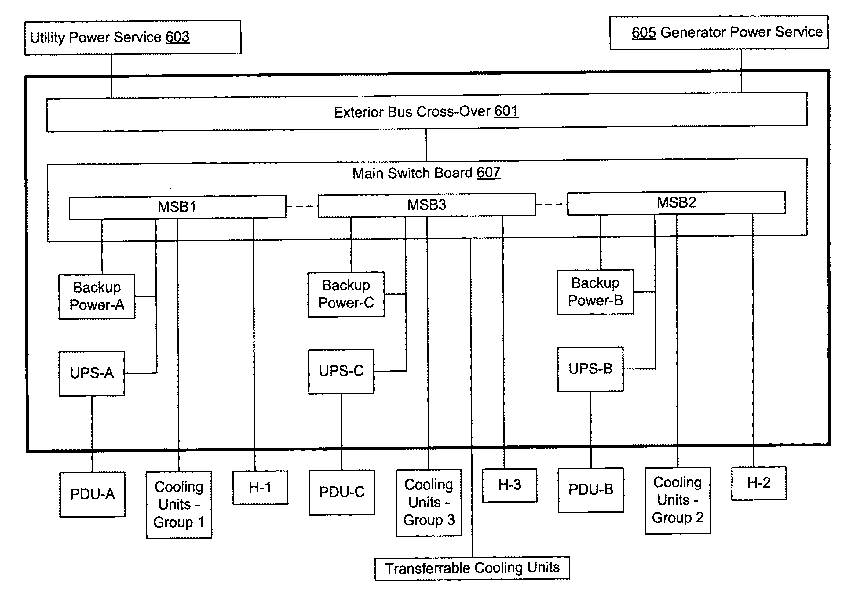
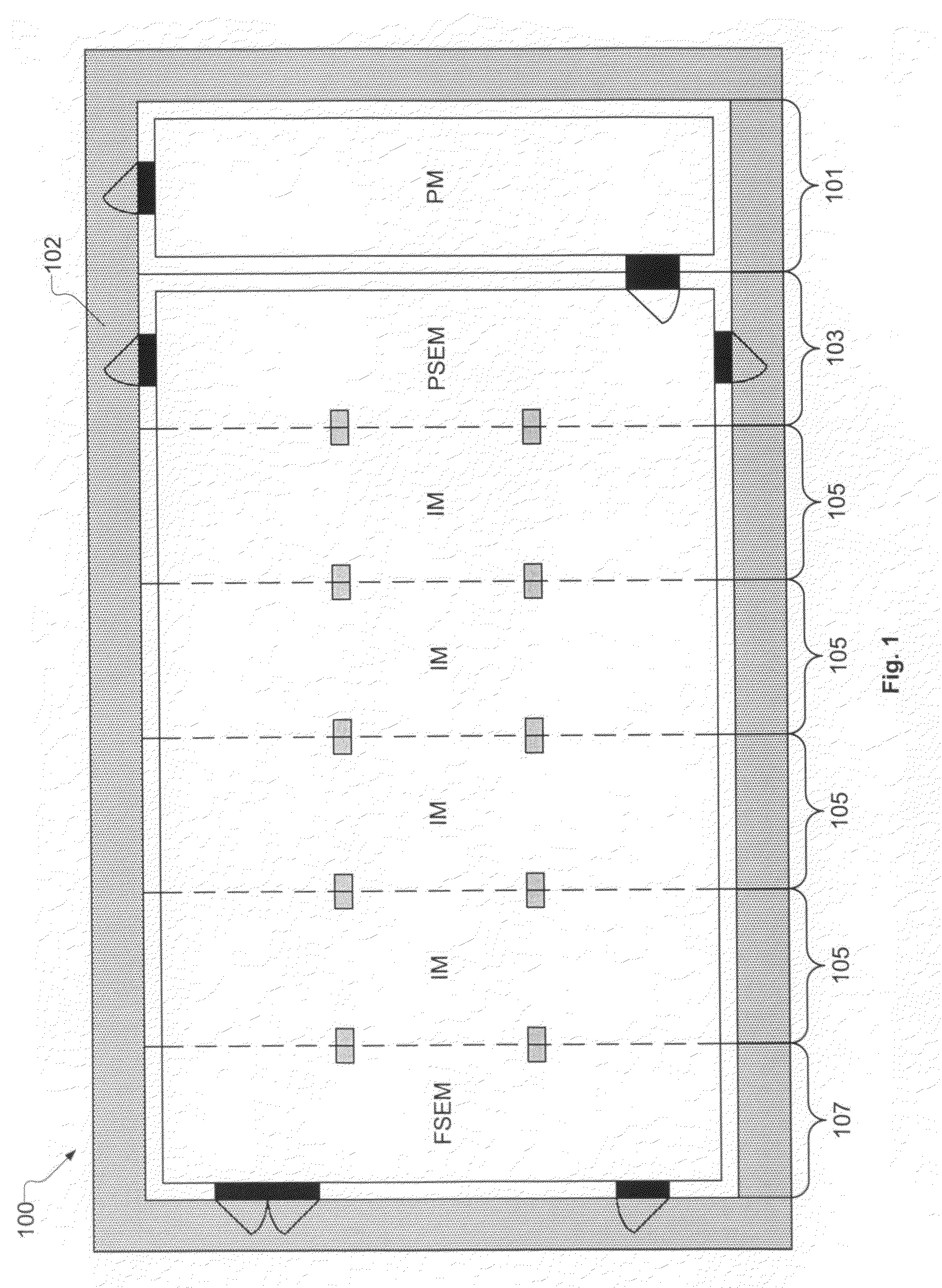
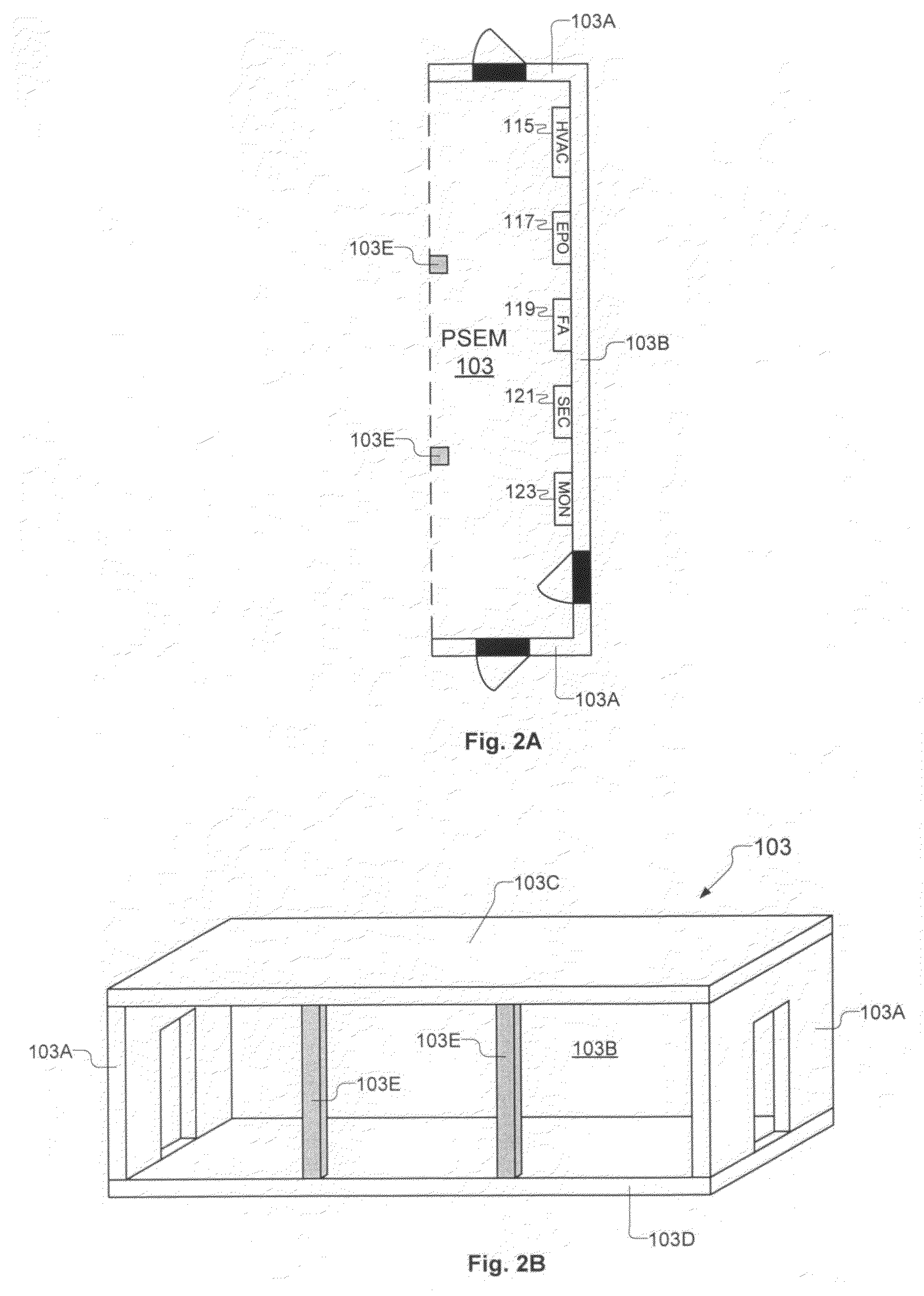
[0019]FIG. 1 shows an exemplary assembled modular data center 100, in accordance with one embodiment of the present invention. The assembled modular data center 100 includes a number of different types of modules, such as a power module 101, a power side end module 103, a number of central modules 105, and a facility side end module 107. The various modules are manufactured off-site (i.e., away from the actual data center assembly location), transported to the data center assembly location, and assembled together at the data center assembly location to ...


PUM


Abstract

A number of structural modules are configured to be secured together and to be secured to a foundation. Each of the structural modules is without one or more sidewalls, such that when the structural modules are secured together they form a building structure that encloses an open region which continuously extends through interiors of the structural modules. Each of the number of structural modules is structurally formed to be independently transported. A power module is configured to be secured to one of the structural modules and to the foundation. The power module is defined as an enclosed structure and is structurally formed to be independently transported. The power module is equipped with electrical components for supplying and distributing electrical power to a pre-defined layout of data equipment to be deployed within the open region of the building structure formed by the number of structural modules.

Description

CLAIM OF PRIORITY[0001]This application claims priority under 35 U.S.C. 119(e) to U.S. Provisional Patent Application No. 61 / 178,921, filed May 15, 2009. This application also claims priority under 35 U.S.C. 119(e) to U.S. Provisional Patent Application No. 61 / 306,382, filed Feb. 19, 2010. Each of the above-identified provisional applications is incorporated herein by reference in its entirety.BACKGROUND[0002]A data center is a structure defined to enclose, secure, maintain, and power a large number of computer systems. The computer systems within the data center are generally rack-mounted computer systems in which a number of removable electronics modules are stacked relative to each other within a support frame. The data center is defined to maintain interior ambient conditions suitable for proper operation of the computer systems therein. Also, the data center is defined to distribute power to the various computer systems therein.[0003]One type of conventional data center is cons...

Claims


Application Information

Patent Timeline
IPC IPC(8): H05K7/00
CPCE04H2001/1283H05K7/1497H05K7/1457E04H2005/005
Inventor BERGTHOLD, RUDYIBARRA, DAVID
Owner NXGEN MODULAR
Learn More