Composite cable

a technology of composite cables and optical fibers, applied in the direction of optical fibers, instruments, fibre mechanical structures, etc., can solve the problems of optical fiber breakage, increase in transmission loss attributable to such bending distortion, and the risk of optical fibers having a bending distortion or the end of the composite cable being unfastened, so as to prevent the increase of transmission loss

Inactive Publication Date: 2010-11-18
HITACHI CABLE
View PDF5 Cites 13 Cited by
  • Summary
  • Abstract
  • Description
  • Claims
  • Application Information

AI Technical Summary

Benefits of technology

[0023]By the present invention, it becomes practicable to obtain such a composite cable as is able to prevent both the unfastening of the cable end from the connector and the occurrence of the bending distortion of the optical fiber, to both of which the expansion and shrinkage of the overall sheath is responsible.
[0024]Further by the present invention, it becomes practicable to provide a composite cable that is suitable for the high-speed transmission of large capacity signals like digital signals preventing increase in the transmission loss caused by the bend of the optical fiber, even if the cable is to be installed in such a place as requires bending a cable.

Problems solved by technology

This may possibly invite a risk of the optical fiber having a bending distortion or the end of the composite cable being unfastened from the fastener in the connector attributable to expansion or shrinkage of the overall sheath.
Particularly, if bending distortion appears in the optical fiber, it may develop into breakage of the optical fiber or into increase in the transmission loss attributable to such bending distortion.
Further, when the composite cable is to be connected to an on-device connector or to be installed in such a place as requires bending a cable, bending applied to the composite cable will cause transmission loss in the optical fiber thereof.
Consequently, the high-speed transmission of large capacity signals like digital signals may be not available.
Particularly, in the case where a local lateral pressure affects the optical fibers in the composite cable, the increase in the transmission loss due to the bending becomes considerable with the high-speed transmission of large capacity signals like digital signals being not available.

Method used


Image

  • Composite cable
  • Composite cable
  • Composite cable

Examples


embodiment 1

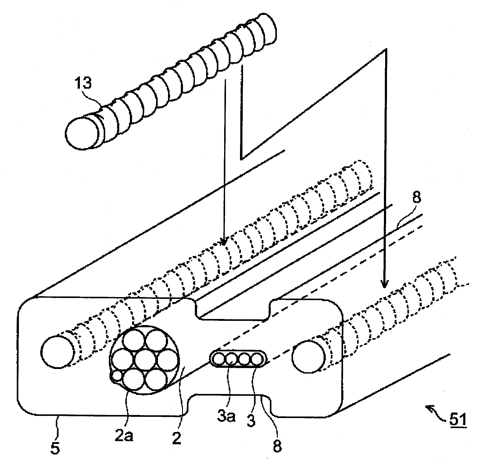
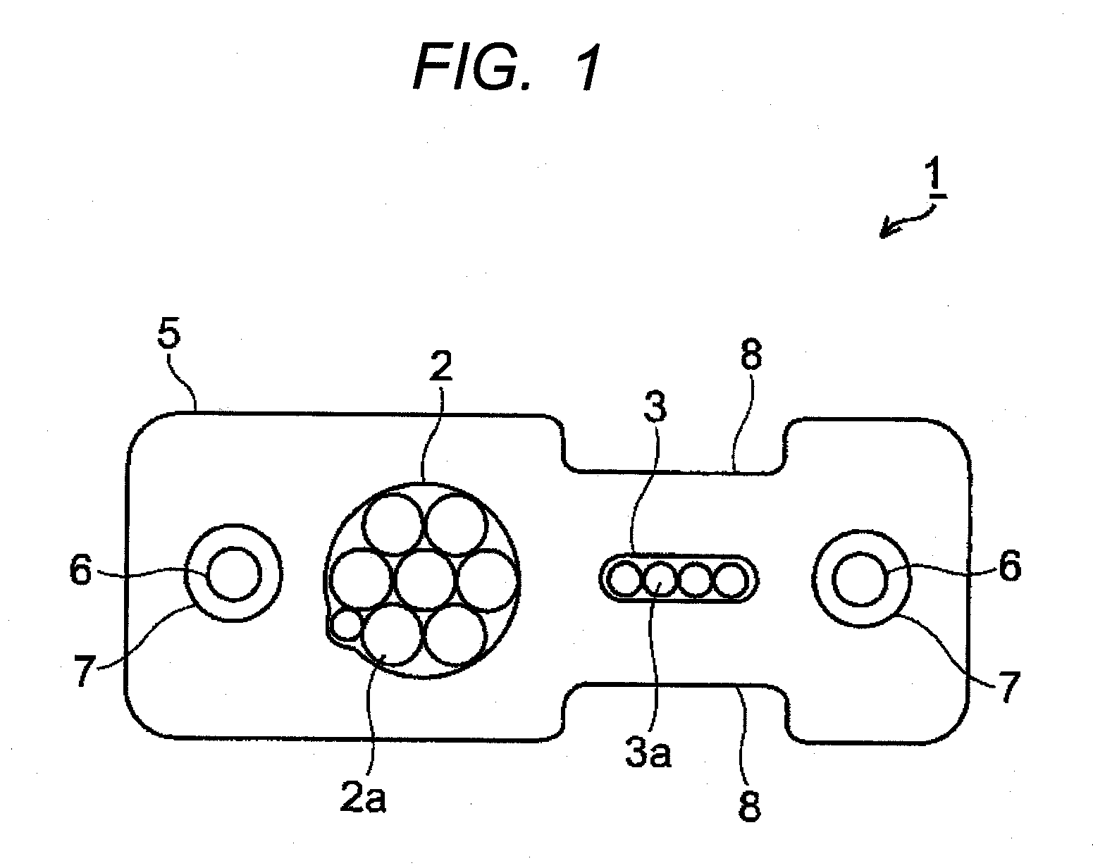
[0046]FIG. 1 illustrates Embodiment 1 of the present invention. As FIG. 1 illustrates, a composite cable 1 by the present invention is comprised of a stranded wire 2 that is a strand of a plurality of (seven in FIG. 1) insulated conductors (metallic wires) 2a each of which is a conductor with insulation covering thereon, an optical fiber ribbon 3 that has a plurality of (four in FIG. 1) optical fibers 3a, each of which is made of quartz or similar material, arranged in a parallel-array (in a row), a deterrent 6, and an overall sheath 5 that covers the stranded wire 2, the optical fiber ribbon 3, and the deterrent 6 in a bundle.

[0047]The stranded wire 2 and the optical fiber ribbon 3 are arranged in a parallel-array (in a row) in the direction along which the optical fibers 3a are parallelly arranged in a row (side-to-side direction across the cross section illustrated in FIG. 1). The stranded wire 2 is used for, for example, power feeding or control signal transmission, and the opti...

embodiment 2

[0066]FIG. 4 illustrates Embodiment 2 of the present invention. A composite cable 21 illustrated in FIG. 4(a) has a different construction from that of Embodiment 1 illustrated in FIG. 1 with respect to the construction of a stranded wire 2 and an optical fiber ribbon 3. Those explanations in Embodiment 1 of the present invention illustrated in FIG. 1 that will be commonly applicable to Embodiment 2 are omitted; and only those aspects different from Embodiment 1 are explained hereunder referring to FIG. 4.

[0067]The composite cable 21 illustrated in FIG. 4(a) has such a construction that each of the both sides in the width direction of the optical fiber ribbon 3, which has four optical fibers 3a arranged in a parallel-array, has one stranded wire 2 being centered at the optical fiber ribbon 3, that is, two stranded wires 2 in total.

[0068]An overall sheath 5 in this embodiment is preferred to be provided with concave portions 8-8 each having a width larger than the width of the optica...

embodiment 3

[0072]FIG. 5 illustrates Embodiment 3 of the present invention. A composite cable 31 illustrated in FIG. 5 is such a composite cable that the stranded wire 2 and the optical fiber ribbon 3 in the composite cable 1 illustrated in FIG. 1 are arranged respectively in the plural number. With respect to arrangement of a stranded wire 2 and an optical fiber ribbon 3 in this embodiment, an example would be such that as illustrated in FIG. 5. In the arrangement example illustrated, an optical fiber ribbon group comprised of: a pile of two optical fiber ribbons 3 disposed in parallel arrangement in the width direction of an overall sheath 5 and another two optical fiber ribbons 3 disposed in the same manner stacked in the thickness direction of the overall sheath 5, and a stranded wire group comprised of two stranded wires 2 disposed in parallel arrangement in the width direction of the overall sheath 5, are arrayed in a parallel arrangement in the width direction of the overall sheath 5. Pr...


PUM


Abstract

A composite cable that is able to prevent both the unfastening of the cable end from the connector and the occurrence of the bending distortion of the optical fiber, to both of which the expansion and shrinkage of the overall sheath is responsible, is provided. The composite cable comprises a stranded wire that is a strand of a plurality of insulated conductors each of which is a conductor with insulation covering thereon, an optical fiber ribbon that has a plurality of optical fibers parallelly-arranged in a row, and an overall sheath that covers the stranded wire and the optical fiber ribbon in a bundle, wherein the composite cable has a deterrent positioned on outer side of the stranded wire and the optical fiber ribbon parallelly-arranged in a row along the width direction of the overall sheath for deterring expansion and shrinkage of the overall sheath. Further, the composite cable has a bonding jacket between the deterrent and the overall sheath for making the deterrent adhere to the overall sheath; alternatively, the deterrent has a patterned indented shape on the surface thereof for making the deterrent adhere to the overall sheath.

Description

TECHNICAL FIELD[0001]The present invention relates to a composite cable comprised of a plurality of metallic wires and optical fibers.BACKGROUND ART[0002]In recent years, transmission on digital signals has been used for a large capacity high-speed transmission without deterioration of image signals of such as photos and movies between devices like computers and liquid crystal displays.[0003]The transmission between such devices has used a composite cable that is comprised of insulated conductors (metallic wires) for power feed and control signal transmission and optical fibers for large capacity high-speed transmission of digital signals, wherein these plural metallic wires and optical fibers are covered in a bundle with an overall sheath (refer to JP2006-310197A, for example).[0004]FIG. 20 illustrates an example of a composite cable with its end fixed on a connector.[0005]A composite cable 100, an example of such a composite cable as is described above, is connected to a device th...

Claims


Application Information

Patent Timeline
Patent Type & Authority Applications(United States)
IPC IPC(8): G02B6/44H02G3/00
CPCG02B6/4403H02G3/266G02B6/4416
Inventor KOJIMA, SEIJISUZUKI, KANAKONAMEKAWA, YOSHIKAZU
Owner HITACHI CABLE
Why Eureka
Try Eureka