Exhaust device, image forming apparatus including the same, recording medium on which control program for exhaust device is recorded

Active Publication Date: 2010-11-18
SHARP KK
View PDF3 Cites 2 Cited by
  • Summary
  • Abstract
  • Description
  • Claims
  • Application Information

AI Technical Summary

Benefits of technology

[0012]An object of the invention is to provide an exhaust device efficiently discharging the ozone and discharge products in an image forming apparatus to suppress the deterioration of image quality of printing and to suppress unneces

Problems solved by technology

There is a case where a brush-shaped or roller-shaped contact-type device used in contact with a target is used as a charging device and a transfer device, but the roller-shaped or brush-shaped charging device and transfer device come into contact with a photoreceptor, an intermediate transfer belt, or similar to cause abrasion deterioration of the photoreceptor or the intermediate transfer belt.
The corona charging device is suitable for image forming apparatus with the high printing speed, but it is difficult to avoid generating a discharge product such as ozone (O3) and nitrogen oxide (NOx) in the device.
When the ozone with high concentration is generated in the image forming apparatus as described above

Method used


Image

  • Exhaust device, image forming apparatus including the same, recording medium on which control program for exhaust device is recorded
  • Exhaust device, image forming apparatus including the same, recording medium on which control program for exhaust device is recorded
  • Exhaust device, image forming apparatus including the same, recording medium on which control program for exhaust device is recorded

Examples


Embodiment Construction

[0045]Now referring to the drawings, preferred embodiments of the invention are described below.

[0046](Image Forming Apparatus)

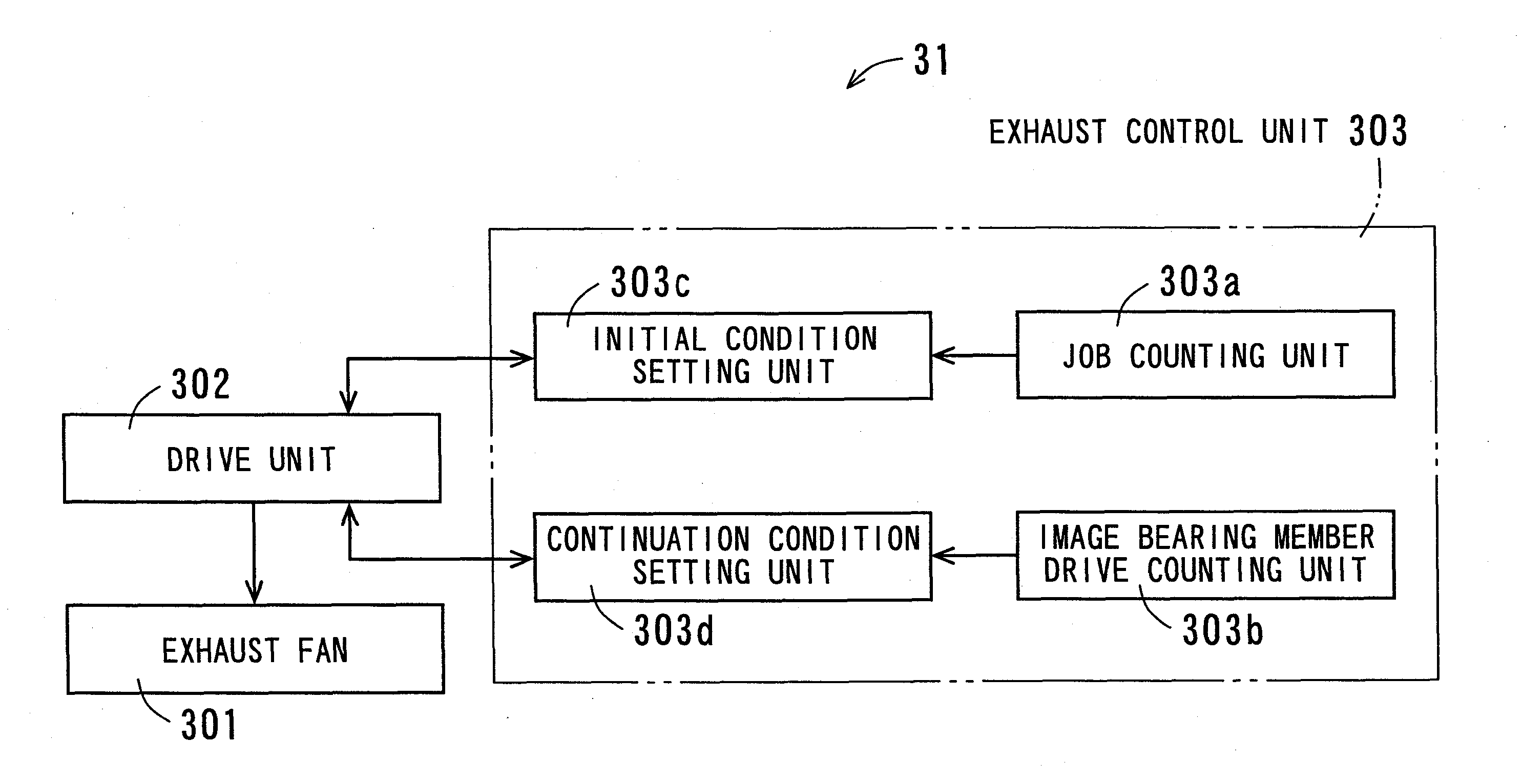
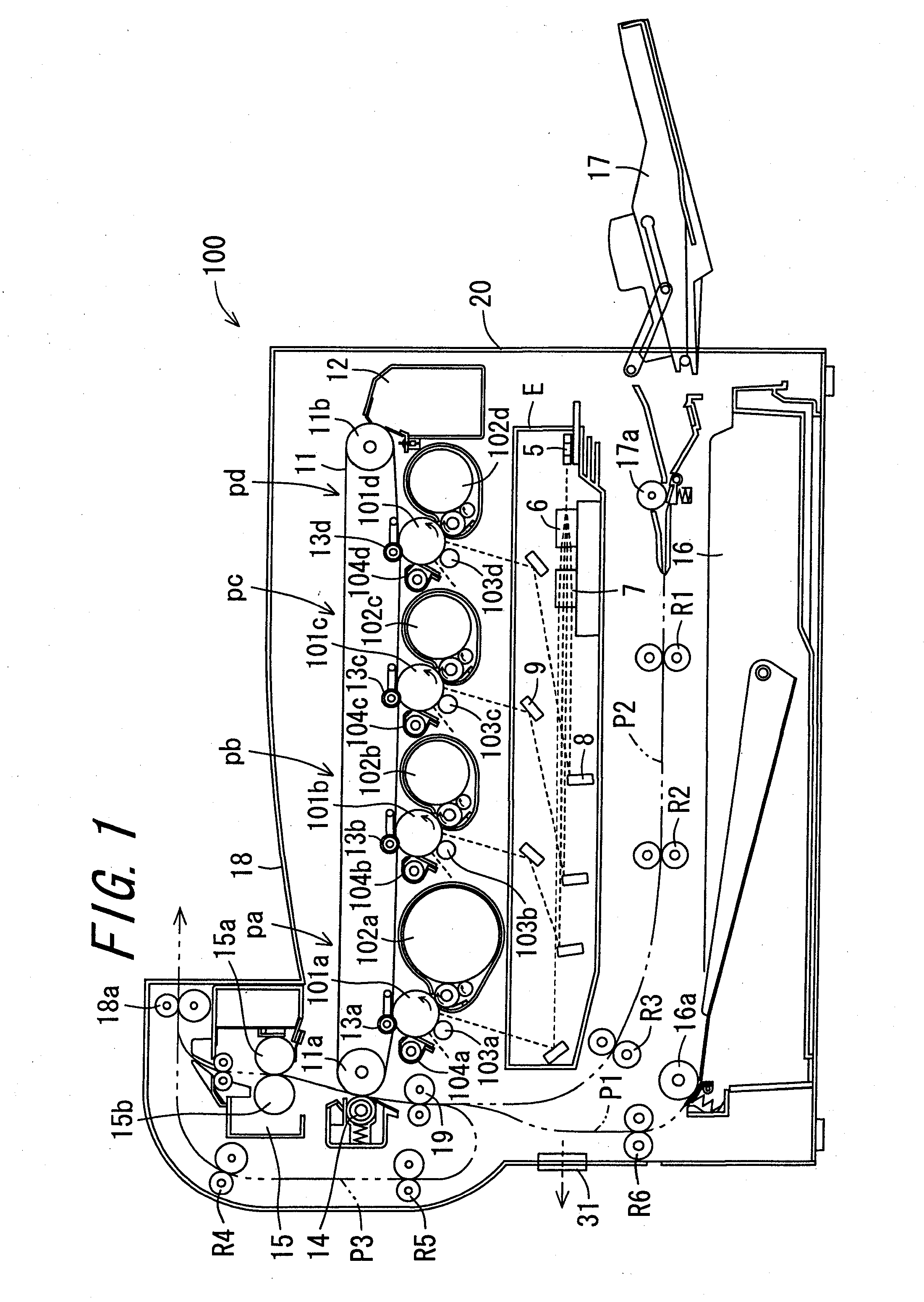
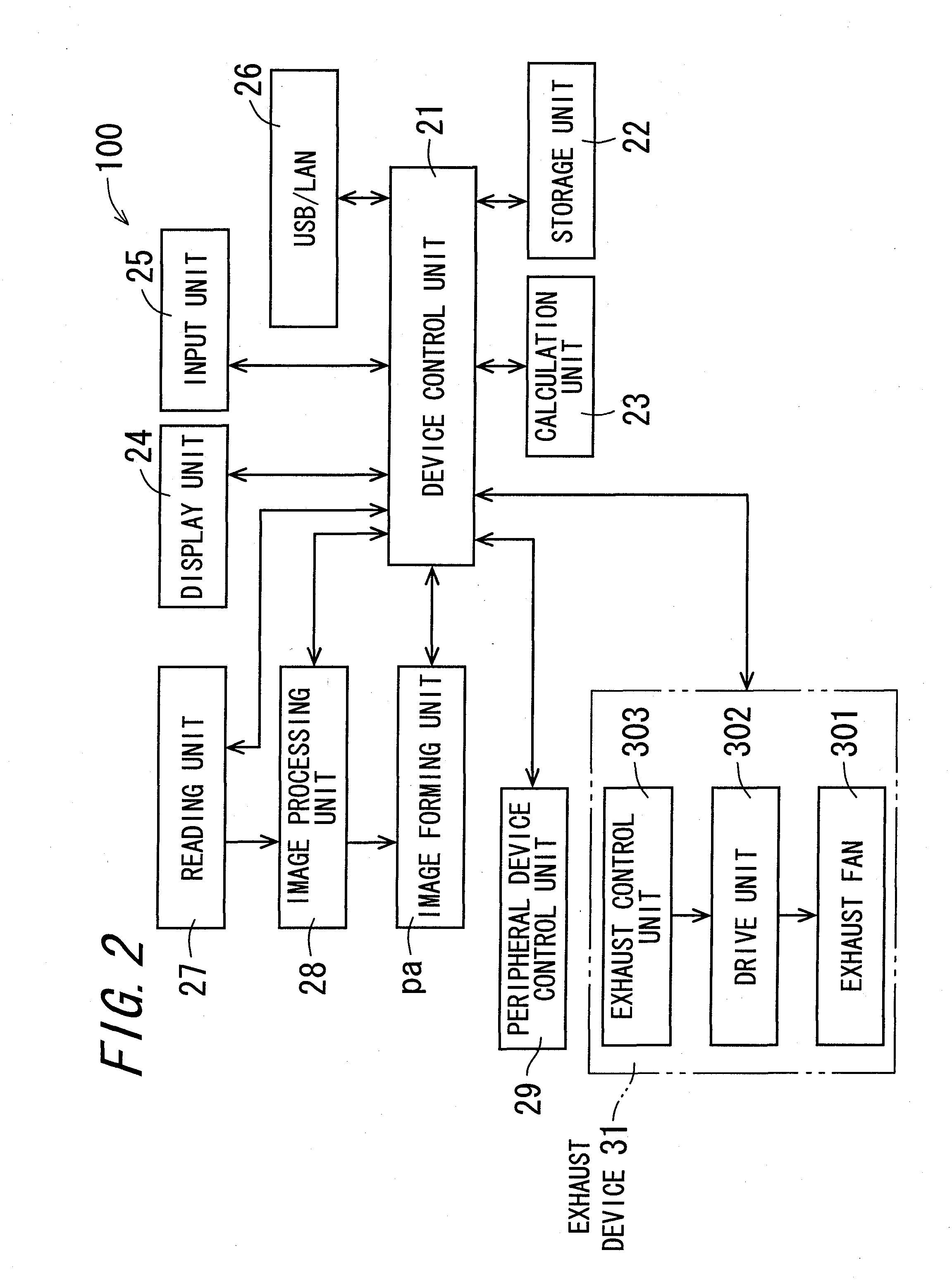
[0047]FIG. 1 is a diagram illustrating a configuration of an image forming apparatus 100 provided with an exhaust device 31 according to an embodiment of the invention. FIG. 2 is a block diagram illustrating an electrical configuration of the image forming apparatus 100.

[0048]A laser printer which forms a multi-color or single-color image on a recording material such as paper based on image data inputted from the outside or image data obtained by reading a document will be described as an example of the image forming apparatus 100.

[0049]As shown in FIG. 1 and FIG. 2, the image forming apparatus 100 is provided with an exposure unit E, four image forming units pa, pb, pc, and pd, an intermediate transfer belt 11, a secondary transfer unit 14, a fixing unit 15, an internal paper feeding unit 16, an manual paper feeding unit 17, a paper discharging unit 18, and...


PUM


Abstract

An exhaust device provided in an image forming apparatus is provided. In the exhaust device, an initial condition setting unit sets an initial drive output value of a exhaust fan at a time of starting an image forming operation based on a calculation value calculated by an image bearing member drive counting unit. A drive unit drives the exhaust fan to start to discharge air in the image forming apparatus. A continuation condition setting unit sets a continuation drive condition at a time of continuously driving the exhaust fan from a point in time when ending the image forming operation based on a count value of the number of image formation by the job counting unit 303a. A drive unit drives the exhaust fan with the continuation drive condition to continuously discharge the air in the image forming apparatus.

Description

CROSS-REFERENCE TO RELATED APPLICATION[0001]This application claims priority to Japanese Patent Application No. 2009-118055, which was filed on May 14, 2009, the contents of which are incorporated herein by reference in its entirety.BACKGROUND OF THE INVENTION[0002]1. Field of the Invention[0003]The present invention relates to an exhaust device for discharging air in an image forming apparatus to an outside of the image forming apparatus and an image forming apparatus provided with the same, and to a computer readable recording medium on which a control program for the exhaust device is recorded.[0004]2. Description of the Related Art[0005]In electrophotographic image forming apparatuses such as copiers, printers, and facsimiles, a photoreceptor provided with a photosensitive layer including a photoconductive material on a surface thereof as an image bearing member is used, electric charges are applied onto the surface of the photoreceptor to uniformly charge the surface by a charg...

Claims


Application Information

Patent Timeline
IPC IPC(8): G03G21/20
CPCG03G21/206
Inventor SAKUWA, TOHRU
Owner SHARP KK
Why Eureka
Try Eureka