Fluid pump assembly

Inactive Publication Date: 2010-11-18
LILY CORP
View PDF11 Cites 4 Cited by
  • Summary
  • Abstract
  • Description
  • Claims
  • Application Information

AI Technical Summary

Benefits of technology

[0011]An advantage of the present invention is that fluid which leaks past the pressure loaded seal is returned to the fluid inlet of the pump, thereby reducing spillage into the work area and reducing raw material cost.
is that fluid which leaks past the pressure loaded seal is returned to the fluid inlet of the pump, thereby reducing spillage into the work area and reducing raw material cost.

Problems solved by technology

A problem with known pump arrangements of the type described above is that they tend to be relatively large, complex and expensive.
Another problem is that the pumped fluid can sometimes leak past the seals within the pump.
In the case of an epoxy, this can cause personnel slippage problems, increases material costs, can set up and harden in undesirable locations, and can cause undesirable odors.

Method used


Image

  • Fluid pump assembly
  • Fluid pump assembly
  • Fluid pump assembly

Examples


Embodiment Construction

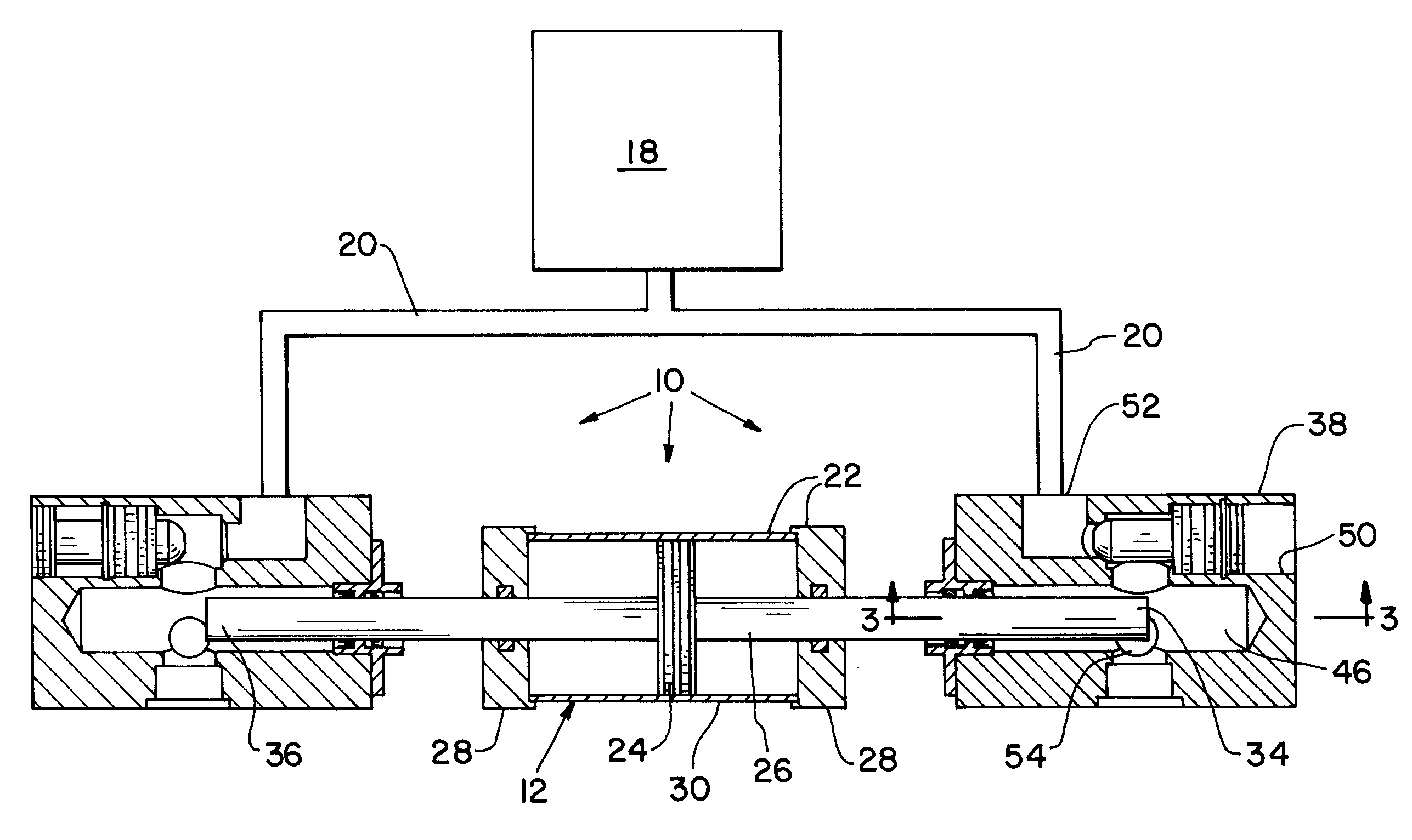
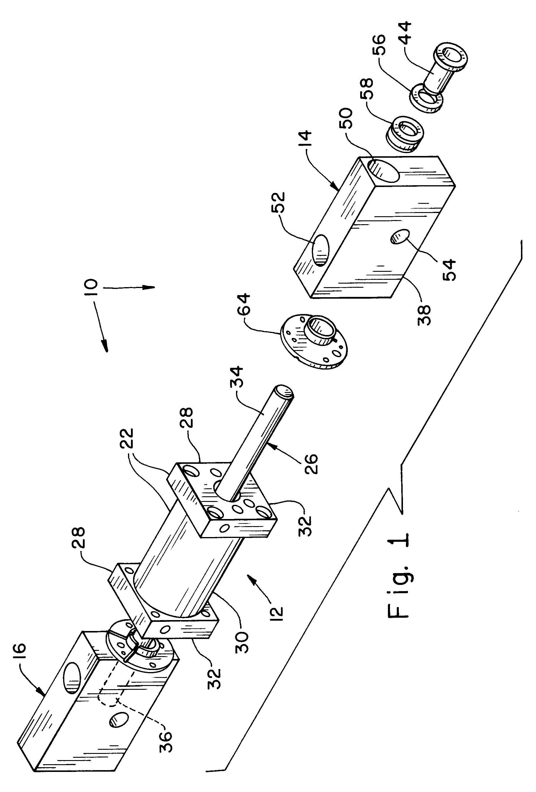
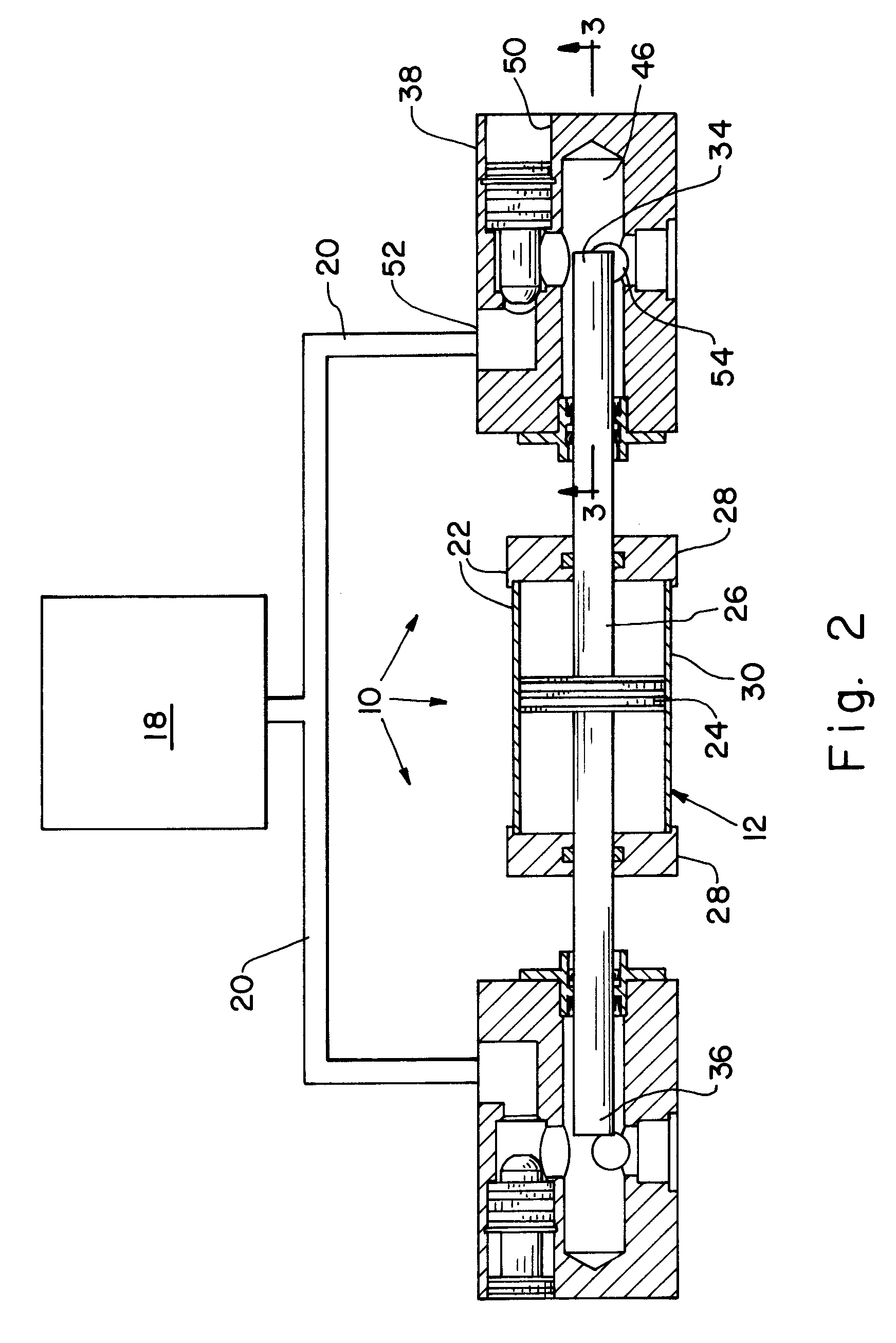
[0023]Referring now to the drawings, and more particularly to FIGS. 1 and 2, there is shown an embodiment of a fluid pump assembly 10 of the present invention which generally includes a double acting fluid cylinder 12, a first pump 14, and a second pump 16. In the embodiment shown, fluid pump assembly 10 is used for pumping one component of a two part epoxy from a hopper 18. However, it is to be understood that fluid pump assembly 10 can be used for pumping other types of fluids, depending upon the application. Hopper 18 is in fluid communication with each of first pump 14 and second pump 16 via a suitable fluid line 20.

[0024]Fluid cylinder 12 is configured as a double acting pneumatic cylinder in the embodiment shown, but could also be configured as a hydraulic cylinder, depending on the application. Fluid cylinder 12 generally includes a housing 22, piston 24, and piston rod 26. Housing 22 includes a pair of end caps 28 mounted to opposite ends of a cylinder 30. End caps 28 and cy...


PUM


Abstract

A fluid pump assembly includes a double acting fluid cylinder with a housing, a piston reciprocally disposed within the housing, and a piston rod carrying the piston and extending from the housing. The piston rod has an end. A pump includes a pump body, a pressure loaded seal and a wiper seal. The pump body has a fluid inlet, a pump chamber and a rod port. The inlet is configured for receiving a fluid to be pumped and is in fluid communication with the pump chamber. The piston rod extends through the rod port and the end is positioned within the pump chamber. The pressure loaded seal is positioned within the rod port around the piston rod and has a pressure loaded end face toward the pump chamber. The wiper seal is positioned within the rod port around the piston rod on a side of the pressure loaded seal opposite from the pump chamber. The pump body further has a scavenging groove in an area between the pressure loaded seal and the wiper seal. The scavenging groove is in fluid communication with the inlet, whereby any fluid which leaks past the pressure loaded seal is returned to the inlet.

Description

CROSS REFERENCE TO RELATED APPLICATIONS[0001]This is a continuation-in-part of U.S. patent application Ser. No. 12 / 433,914, entitled “FLUID PUMP ASSEMBLY”, filed May 1, 2009, which is incorporated herein by reference.BACKGROUND OF THE INVENTION[0002]1. Field of the Invention[0003]The present invention relates to fluid pumps, and, more particularly, to reciprocating piston type fluid pumps.[0004]2. Description of the Related Art[0005]Fluid pumps are utilized for various purposes. One such use is to pump an epoxy into a crack in concrete, such as in a wall or floor of a building. The epoxy typically is a two-part epoxy with a catalyst and a base. The catalyst is kept in one supply hopper and the base is kept in another supply hopper. Separate pumps are usually used to separately pump the catalyst and base to a mixing unit immediately before application within the crack(s). An example of a pump arrangement used to pump an epoxy is disclosed in U.S. Pat. No. 4,828,148, also invented by ...

Claims


Application Information

Patent Timeline
IPC IPC(8): F04B5/02F04B23/06
CPCF04B23/06
Inventor TROUT, JOHN F.
Owner LILY CORP
Why Eureka
Try Eureka