Polyaxial Dental Implant

a dental implant and polyaxial technology, applied in dental implants, dental surgery, medical science, etc., can solve the problems of root-form implants, dental implants generally, and prolonging the patient's exposure to anesthesia,

Inactive Publication Date: 2010-11-18
CUSTOM SPINE INC
View PDF40 Cites 45 Cited by
  • Summary
  • Abstract
  • Description
  • Claims
  • Application Information

AI Technical Summary

Problems solved by technology

The typical abutment, however, is often unwieldy, due to the number of separate components, and frequently results in prolonging the patient's exposure to anesthesia.
Though widely accepted by dental practitioners, dental implants generally, and root-form implants in particular, are not without problems.
For example, the neck portions of commercially available angled abutments have fixed angular displacements with respect to their base portions, which limit their usefulness.
However, since only discrete orientation angles are available, it is often necessary to modify the abutment to achieve the requisite angular orientation, which can be a labor intensive and costly process.
In some cases the necessary orie

Method used


Image

  • Polyaxial Dental Implant
  • Polyaxial Dental Implant
  • Polyaxial Dental Implant

Examples


Embodiment Construction

[0027]The embodiments herein and the various features and advantageous details thereof are explained more fully with reference to the non-limiting embodiments that are illustrated in the accompanying drawings and detailed in the following description. Descriptions of well-known components and processing techniques are omitted so as to not unnecessarily obscure the embodiments herein. The examples used herein are intended merely to facilitate an understanding of ways in which the embodiments herein may be practiced and to further enable those of skill in the art to practice the embodiments herein. Accordingly, the examples should not be construed as limiting the scope of the embodiments herein.

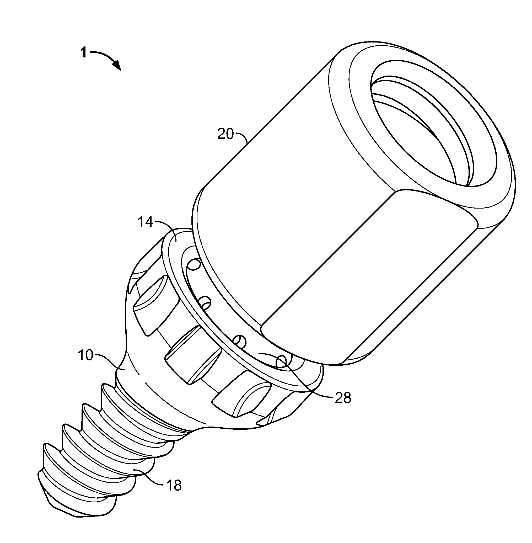
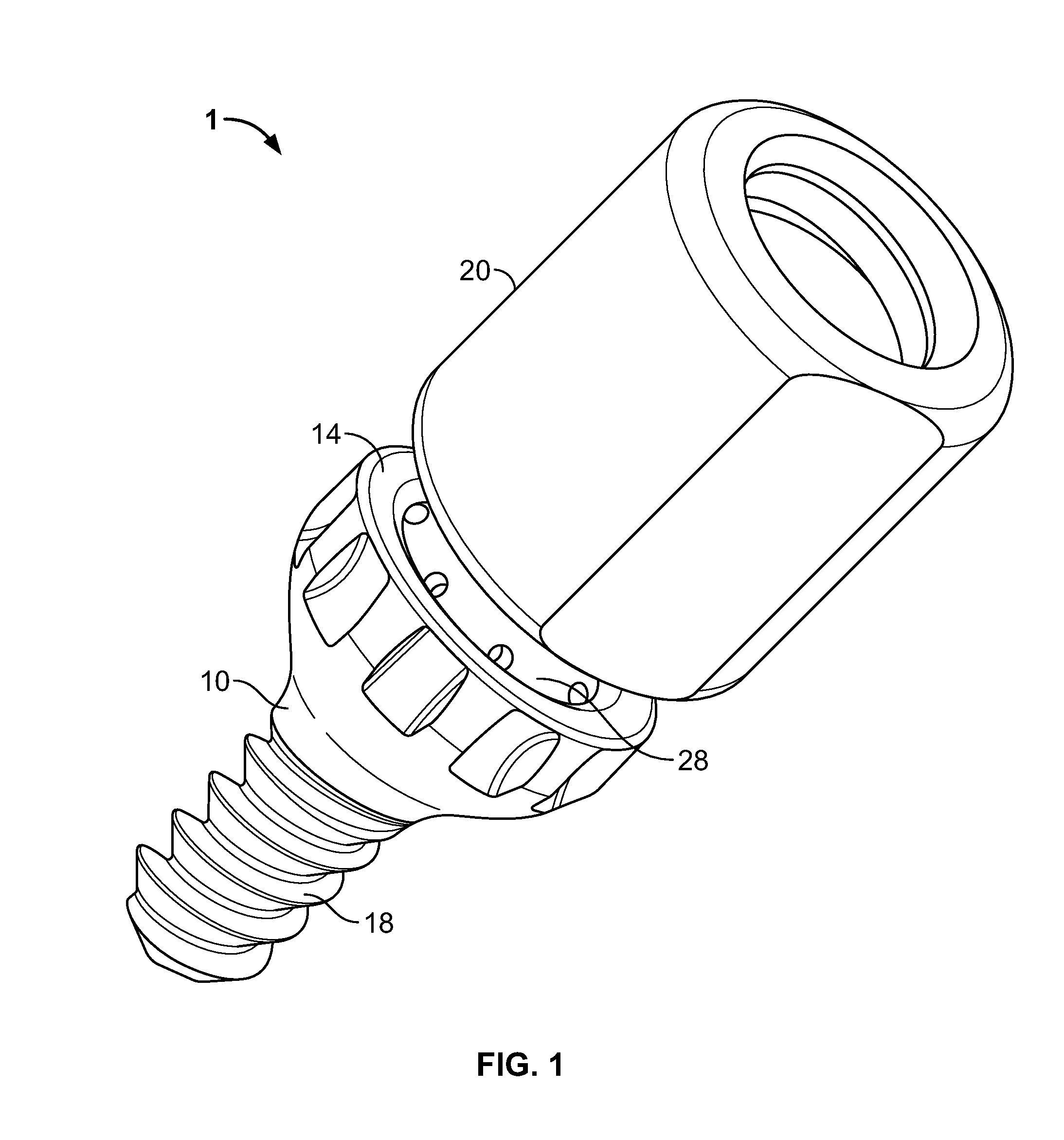
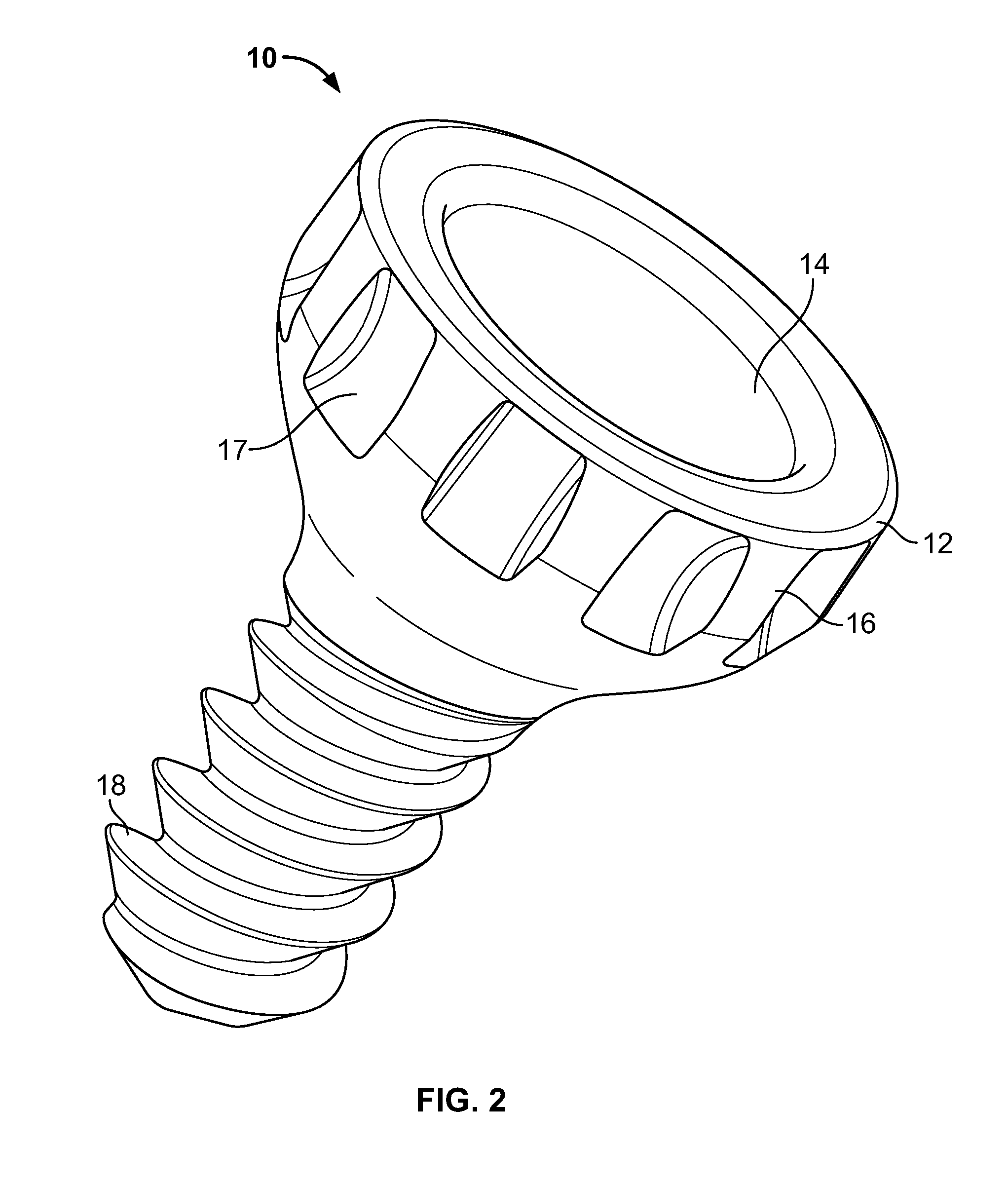
[0028]The embodiments herein provide an improved dental implant device with fewer components than conventional systems and a method of assembly capable of simplifying a surgical procedure using such an improved dental implant device. The improved dental implant assembly overcomes the limitation...


PUM


Abstract

A polyaxial dental implant includes an abutment member that includes a channel bored through a longitudinal axis of the abutment member, and an outwardly protruding and expandable round bulbous body coupled to an end of the abutment member. The implant includes a fixture member coupled to the bulbous body, where the fixture member receives the bulbous body; and a pin engaged within the abutment member via the channel and contacting the bulbous body causing the bulbous body to outwardly expand into the fixture member.

Description

BACKGROUND[0001]1. Technical Field[0002]The embodiments herein generally relate to endosseous dental implants, and, more particularly, to an abutment used to secure a dental prosthesis to an implant fixture.[0003]2. Description of the Related Art[0004]A conventional dental implant device typically consists of two components: an implant fixture and an abutment. An implant fixture is imbedded into a patient's maxilla or mandible bone. An abutment is connected to the fixture and typically forms a support for a prosthesis; i.e., a crown, denture, partial bridge, or bridge. The implant fixture may be surgically implanted into the bone at various angles depending on several factors, such as the number of implants being placed into a corresponding section of edentulous (toothless) bone; the portion of the edentulous bone best suited to successfully support the implant; and the angle chosen by the dental professional in placing the implant. The abutment, however, must be aligned so that the...

Claims


Application Information

Patent Timeline
IPC IPC(8): A61C8/00
CPCA61C8/005A61C8/0068A61C8/0065A61C8/0053
Inventor ABDELGANY, MAHMOUD F.
Owner CUSTOM SPINE INC
Why Eureka
Try Eureka