Al technical title is built by PatSnap Al team. It summarizes the technical point description of the patent document.
a technology of intervertebral discs and tooling, which is applied in the field of cervical intervertebral disc implants, can solve the problems of undesirable progressive fusion of a long sequence of vertebrae, significant pain to the individual suffering from the condition, etc., and achieve the effect of facilitating insertion into the disc spa
Inactive Publication Date: 2010-11-18
HOWMEDICA OSTEONICS CORP
View PDF21 Cites 45 Cited by
Summary
Abstract
Description
Claims
Application Information
AI Technical Summary
This helps you quickly interpret patents by identifying the three key elements:
Problems solved by technology
Method used
Benefits of technology
[0028]In certain preferred embodiments, the top surface of the body desirably tapers toward the bottom surface of the body between the traili
Problems solved by technology
This degeneration of this critical disc material, from the hydrated, elastomeric material that supports the separation and flexibility of the vertebral bones, to a flattened and inflexible state, has profound effects on the mobility (instability and limited ranges of appropriate motion) of the segment, and can cause significant pain to the individual suffering from the condition.
Unfortunately, until the ad
Method used
Image
Click on the blue label to locate the original text in one second.
Reading with bidirectional positioning of images and text.
Examples
Embodiment Construction
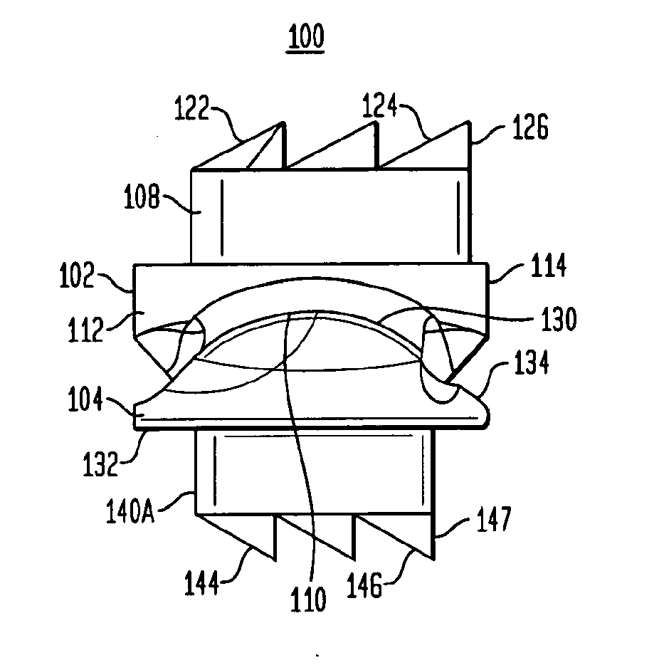
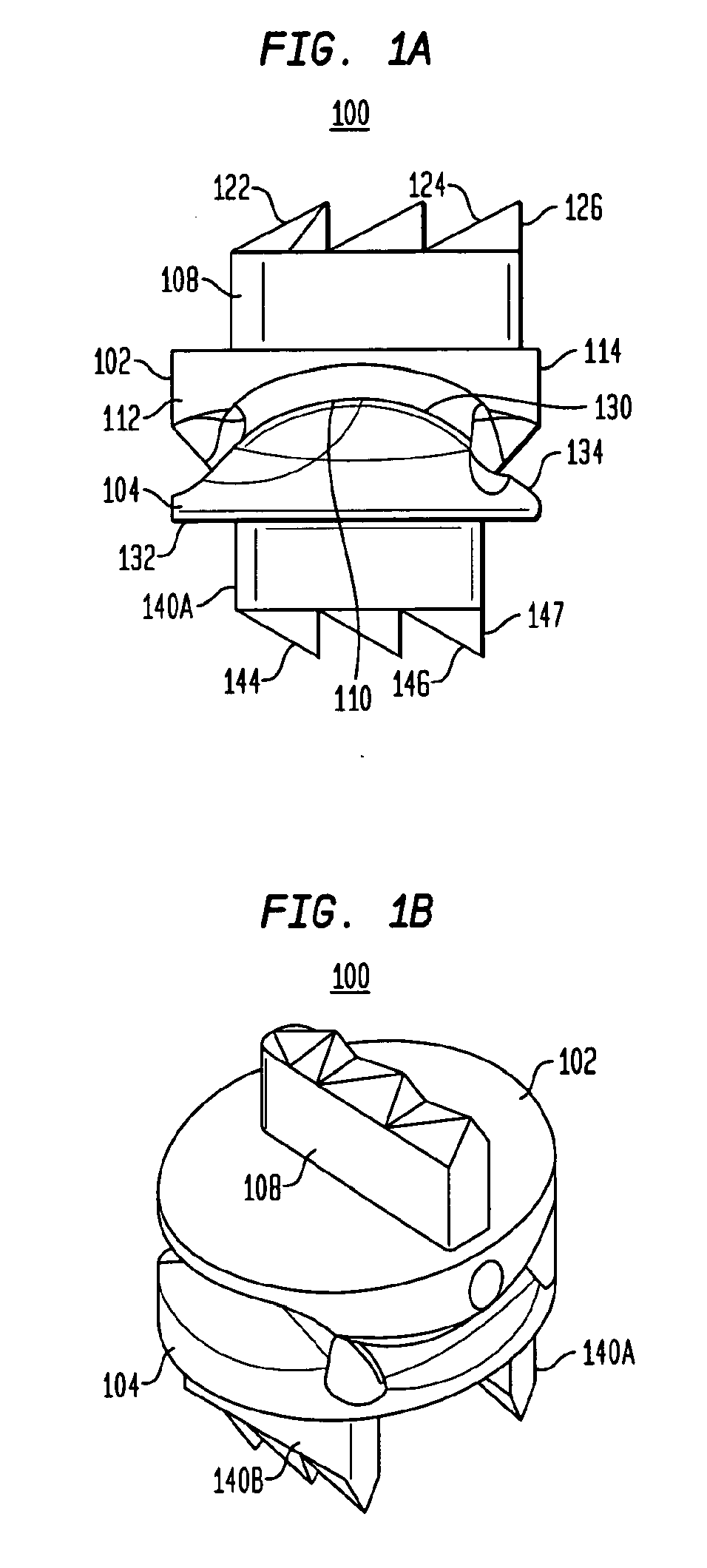
[0062]Referring to FIGS. 1A and 1B, in certain preferred embodiments of the present invention, an intervertebral disc implant 100 includes a top element 102 and a bottom element 104. As will be described in more detail below, the top and bottom elements 102, 104 have opposing articulating surfaces that engage one another. The intervertebral disc implant is adapted to be inserted into a disc space between adjacent vertebrae. In certain preferred embodiments, two or more disc implants can be stacked over one another in two or more successive disc spaces. In still other preferred embodiments, the disc implants are cervical implants.
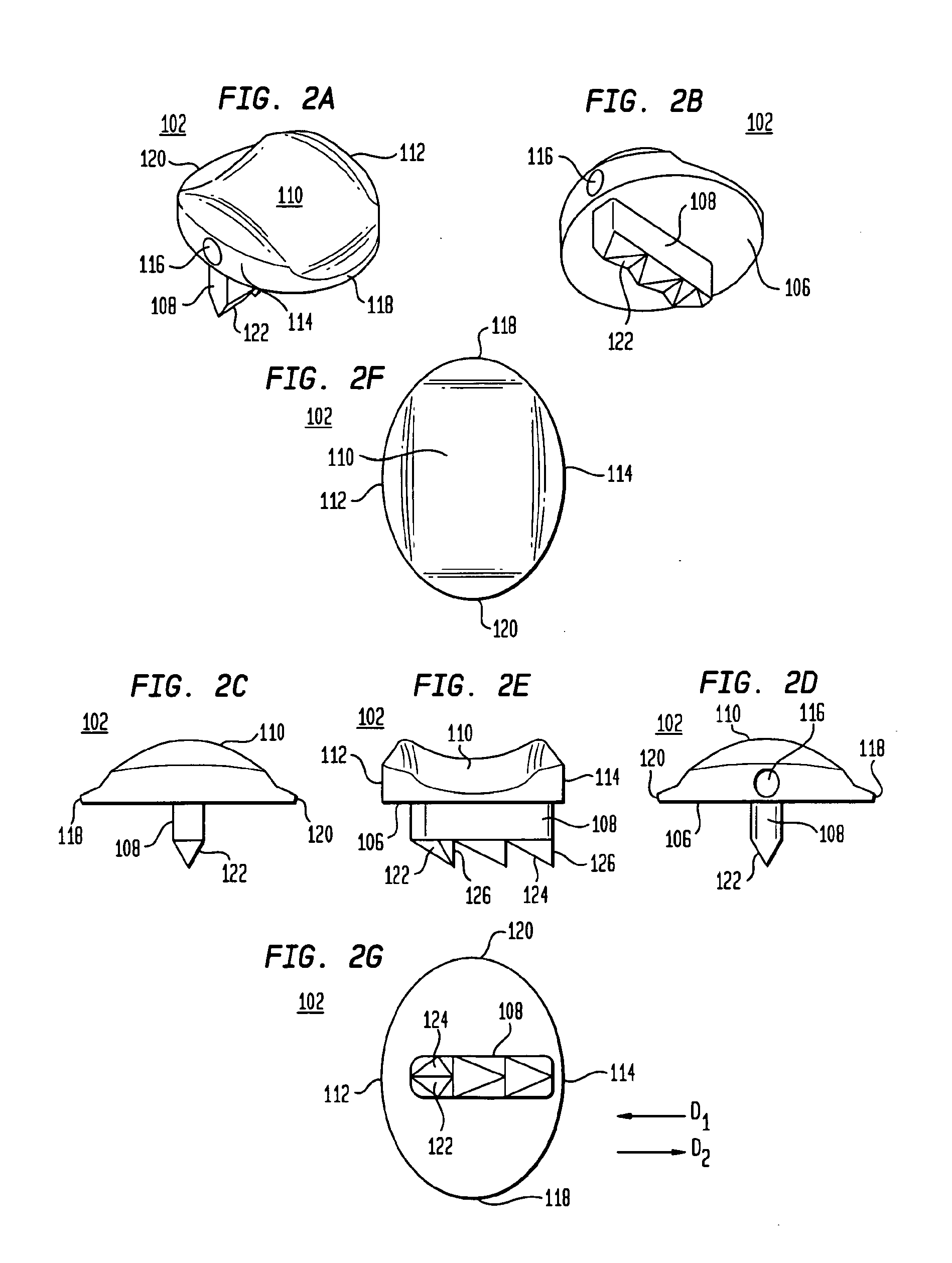
[0063]Referring to FIGS. 2A-2E, the top element 102 includes a first bone engaging surface 106 having a protrusion 108 and a second articulating surface 110. Referring to FIGS. 2E-2G, the top element 102 has a posterior end 112 and an anterior end 114. As shown in FIGS. 2A-2B and 2D, the top element 102 has an opening 116 at the anterior end 114 thereof that...
PUM
Abstract
A kit for preparing an intervertebral disc space for receiving an implant (100) includes a plurality of trials (152) having different sizes. Each trial (152) includes a body (154) insertible into an intervertebral disc space, the body (154) having a leading end (162), a trailing end (164), a top surface (156) and a bottom surface (160), the top surface of the body having a first groove (176) formed therein. Each implant also includes a flange (166) secured to the trailing end (164) of the body (154), the flange (166) having a first channel (180) aligned with the first groove (176), wherein each of the different sized trials has a different flange thickness. The flange thickness controls advancement of a cutting tool such as a chisel (192) into the first groove at the top surface of the trial body, which controls the depth of the cut into vertebral bone.
Description
CROSS-REFERENCE TO RELATED APPLICATIONS[0001]This application claims the benefit of the filing date of U.S. Provisional Patent Application No. 60 / 846,196 filed Sep. 21, 2006, the disclosure of which is hereby incorporated herein by reference.[0002]The present application is related to U.S. patent application Ser. No. 11 / 439,808, filed May 24, 2006, which claims the benefit of U.S. Provisional Patent Application No. 60 / 790,415, filed Apr. 7, 2006, which claims the benefit of U.S. Provisional Patent Application No. 60 / 721,053, filed Sep. 27, 2005, which claims the benefit of U.S. Provisional Patent Application No. 60 / 701,306, filed Jul. 21, 2005, which claims the benefit of U.S. Provisional Patent Application No. 60 / 685,295, filed May 27, 2005, the disclosures of which are hereby incorporated by reference herein.[0003]The present application also relates to U.S. Pat. No. 6,908,484, entitled “Cervical Disc. Replacement” and filed on Mar. 6, 2003; U.S. Pat. No. 6,994,728, entitled “Cerv...
Claims
Application Information
Patent Timeline
Application Date:The date an application was filed.
Publication Date:The date a patent or application was officially published.
First Publication Date:The earliest publication date of a patent with the same application number.
Issue Date:Publication date of the patent grant document.
PCT Entry Date:The Entry date of PCT National Phase.
Estimated Expiry Date:The statutory expiry date of a patent right according to the Patent Law, and it is the longest term of protection that the patent right can achieve without the termination of the patent right due to other reasons(Term extension factor has been taken into account ).
Invalid Date:Actual expiry date is based on effective date or publication date of legal transaction data of invalid patent.