Buoyancy system for an underwater device and associated methods for operating the same

a technology of underwater equipment and buoyancy system, which is applied in underwater equipment, special-purpose vessels, lighting and heating apparatus, etc., can solve the problem of heavy nose of underwater glider, and achieve the effect of improving heat transfer and a large surface area

Inactive Publication Date: 2010-11-25
LOCKHEED MARTIN CORP
View PDF16 Cites 10 Cited by
  • Summary
  • Abstract
  • Description
  • Claims
  • Application Information

AI Technical Summary

Benefits of technology

[0007]This and other objects, advantages and features in accordance with the present invention are provided by a buoyancy system comprising a chamber having a volume associated therewith, and a plurality of bladders within the volume of the chamber. Each bladder may contain a clathrate mixture in a liquid state. The chamber may include at least one opening to allow surrounding water to circulate within the volume. When the chamber is submerged in increasingly frigid surrounding water, the plurality of bladders may expand based on the clathrate mixture changing from the liquid state to a solid state. This thereby increases buoyancy by allowing less water to circulate within the volume of the chamber.
[0008]Similarly, when the chamber ascends in the increasingly warm surrounding water, the plurality of bladders may contract based on the clathrate mixture changing from the solid state to the liquid state. This thereby decreases buoyancy by allowing more water to circulate within the volume of the chamber.
[0012]The buoyancy system may further comprise a respective spacer coupled between adjacent bladders so that the bladders are spaced apart from one another within the volume of the chamber. This advantageously helps with the transfer of heat from the water to the clathrate mixture since the water will surround each bladder, as compared to partially surrounding the bladders when they are bunched up against one another. Moreover, each bladder may be spherically shaped to provide a greater surface area for the water to contact, thereby improving heat transfer.
[0013]The bladders may form a three-dimensional array of bladders. The buoyancy system may further comprise a water permeable enclosure surrounding the plurality of bladders within the volume of the chamber. The water permeable enclosure advantageously prevents anyone of the bladders from escaping the chamber.

Problems solved by technology

This makes the underwater glider's nose heavy.

Method used


Image

  • Buoyancy system for an underwater device and associated methods for operating the same
  • Buoyancy system for an underwater device and associated methods for operating the same
  • Buoyancy system for an underwater device and associated methods for operating the same

Examples


Embodiment Construction

[0023]The present invention will now be described more fully hereinafter with reference to the accompanying drawings, in which preferred embodiments of the invention are shown. This invention may, however, be embodied in many different forms and should not be construed as limited to the embodiments set forth herein. Rather, these embodiments are provided so that this disclosure will be thorough and complete, and will fully convey the scope of the invention to those skilled in the art. Like numbers refer to like elements throughout.

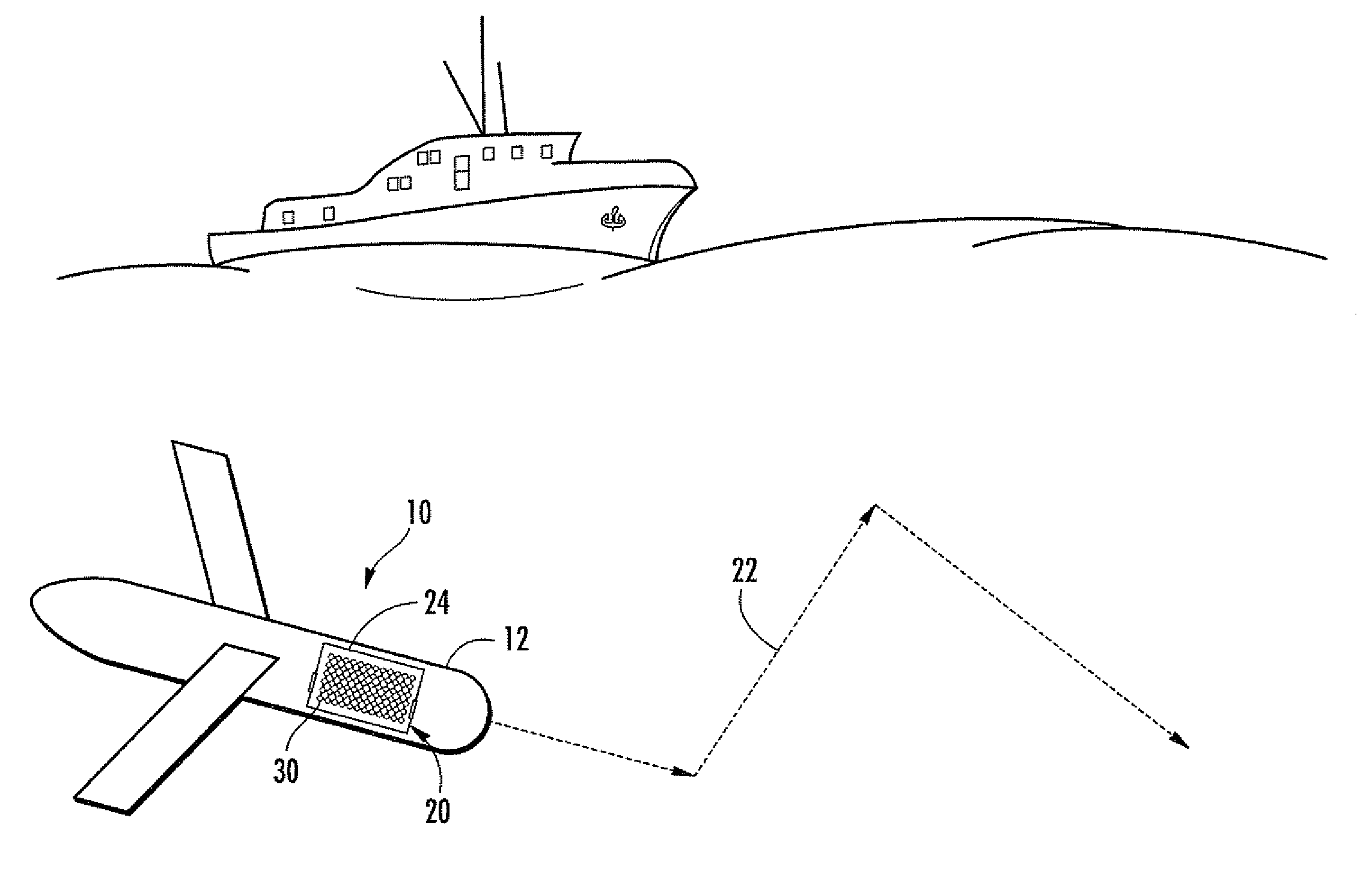
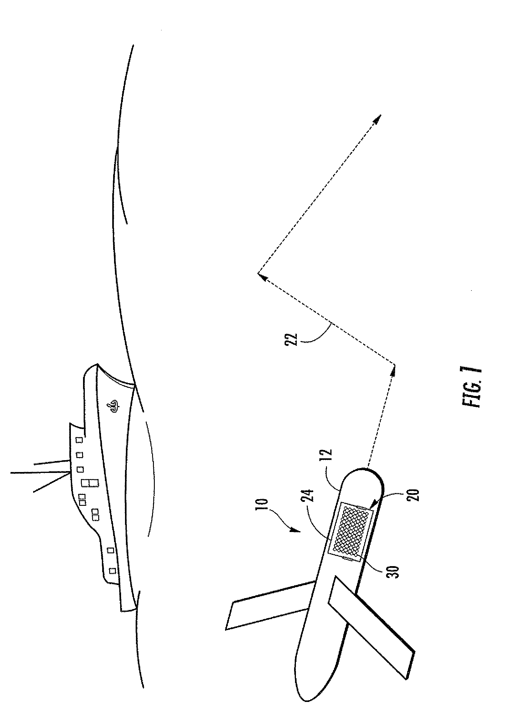
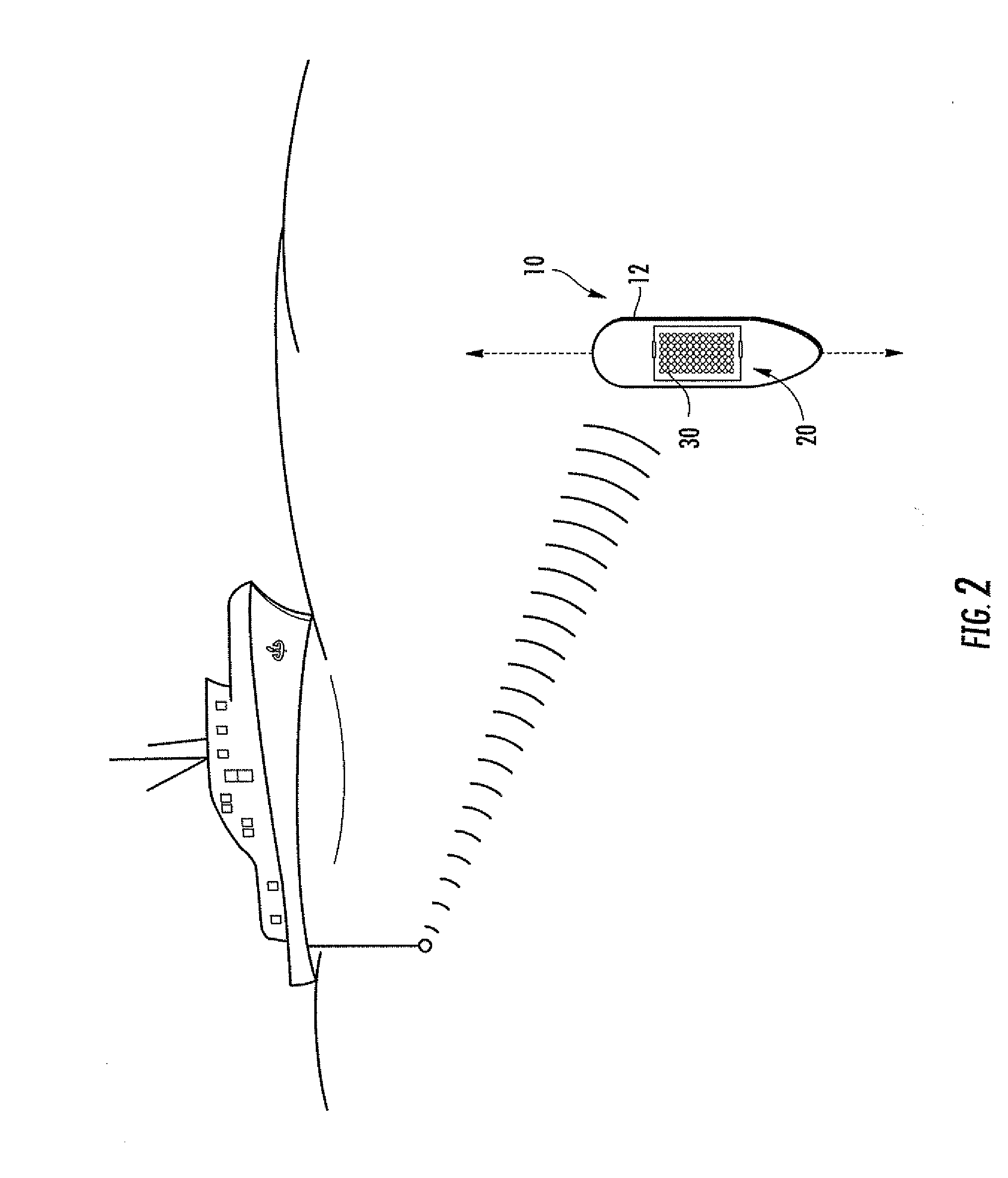
[0024]Referring initially to FIG. 1, an underwater device 10 comprises a housing 12, and a buoyancy system 20 carried by the housing. The underwater device 10 is illustrated as an autonomous underwater glider that may be used to collect subsurface data in an observation region. The underwater glider is neutrally buoyant, and travels through the water in a saw-tooth-sampling pattern 22 by using the buoyancy system 20 to change its buoyancy. Although the und...


PUM


Abstract

A buoyancy system includes a chamber having a volume associated therewith, and bladders within the volume of the chamber. Each bladder contains a clathrate mixture in a liquid state. The chamber includes an opening to allow surrounding water to circulate within the volume and contact the bladders. As the chamber is submerged in the surrounding water, the bladders expand based on the clathrate mixture changing from the liquid state to a solid state. This changes buoyancy by allowing less water to circulate within the volume of the chamber.

Description

FIELD OF THE INVENTION [0001]The present invention relates to the field of underwater devices, and more particularly, to a buoyancy system for controlling buoyancy of an underwater device.BACKGROUND OF THE INVENTION [0002]An underwater glider is a type of underwater device that collects subsurface data in an observation region. The underwater glider is typically a torpedo shaped, winged device that moves through the water in a saw-tooth sampling pattern by changing its buoyancy. The underwater glider is neutrally buoyant, and typically includes a buoyancy system in its nose section.[0003]The buoyancy system may be based on a displacement piston. To diver the displacement piston moves water into nose section of the underwater device. This makes the underwater glider's nose heavy. To ascend, water is pushed out of the nose section by the displacement piston. This makes the underwater glider's nose lighter.[0004]Even in view of the advances made in buoyancy systems, there is still a ne...

Claims


Application Information

Patent Timeline
Patent Type & Authority Applications(United States)
IPC IPC(8): B63G8/14B63G8/18B63G8/22
CPCB63B22/18B63G8/14F28D20/023B63G2008/004B63G8/24
Inventor HERBEK, MATTHEWDIETZEN, ROBERTPOWELL, BRADENBLANCHETTE, KENNETHDAY, SEANGRIES, MATTHEWRAPP, JOHNASCARI, MATTHEWFINI, MARIA
Owner LOCKHEED MARTIN CORP
Why Eureka
Try Eureka