
Seal leakage gas recovery system

a gas recovery and seal technology, applied in liquid fuel engines, process and machine control, instruments, etc., can solve the problem of high undesirable discharge of process fluid into the atmospher

Active Publication Date: 2010-11-25
FLOWSERVE MANAGEMENT CO
View PDF6 Cites 11 Cited by
  • Summary
  • Abstract
  • Description
  • Claims
  • Application Information

AI Technical Summary

Problems solved by technology

However, discharge of such process fluid into the atmosphere is highly undesirable, and therefore, the invention relates to a recovery system for recovering any leakage across the seal rings to thereby prevent seal leakage from leaking to the ambient environment.

Method used


Image

  • Seal leakage gas recovery system
  • Seal leakage gas recovery system
  • Seal leakage gas recovery system

Examples


Embodiment Construction

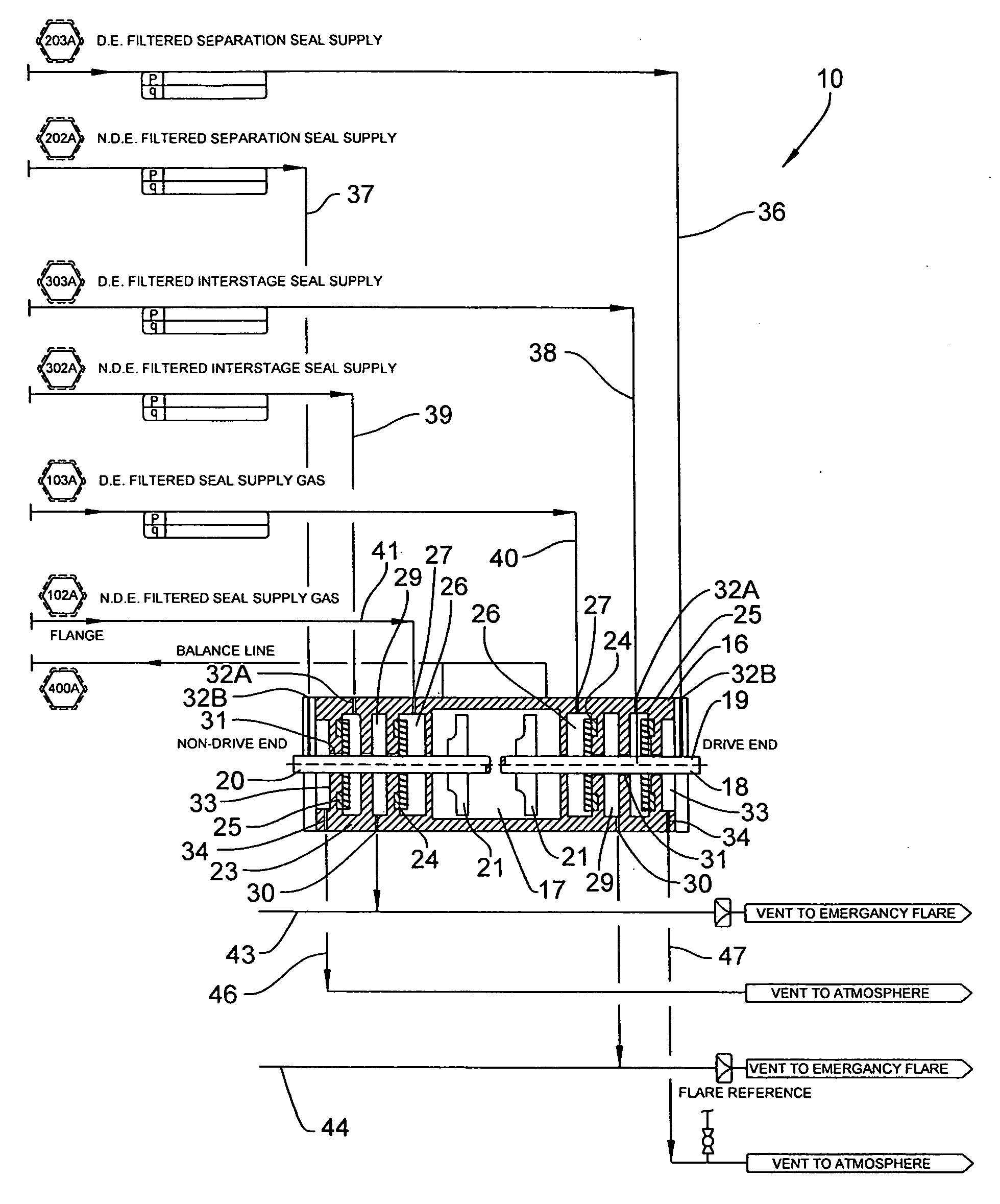
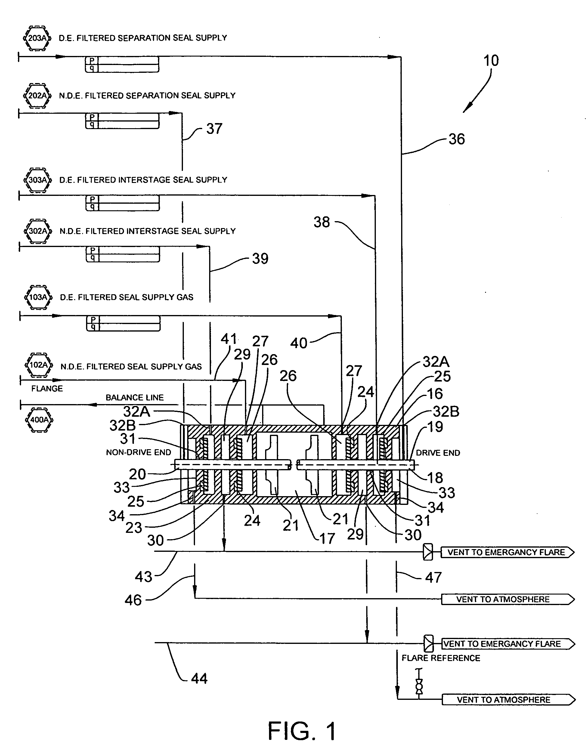
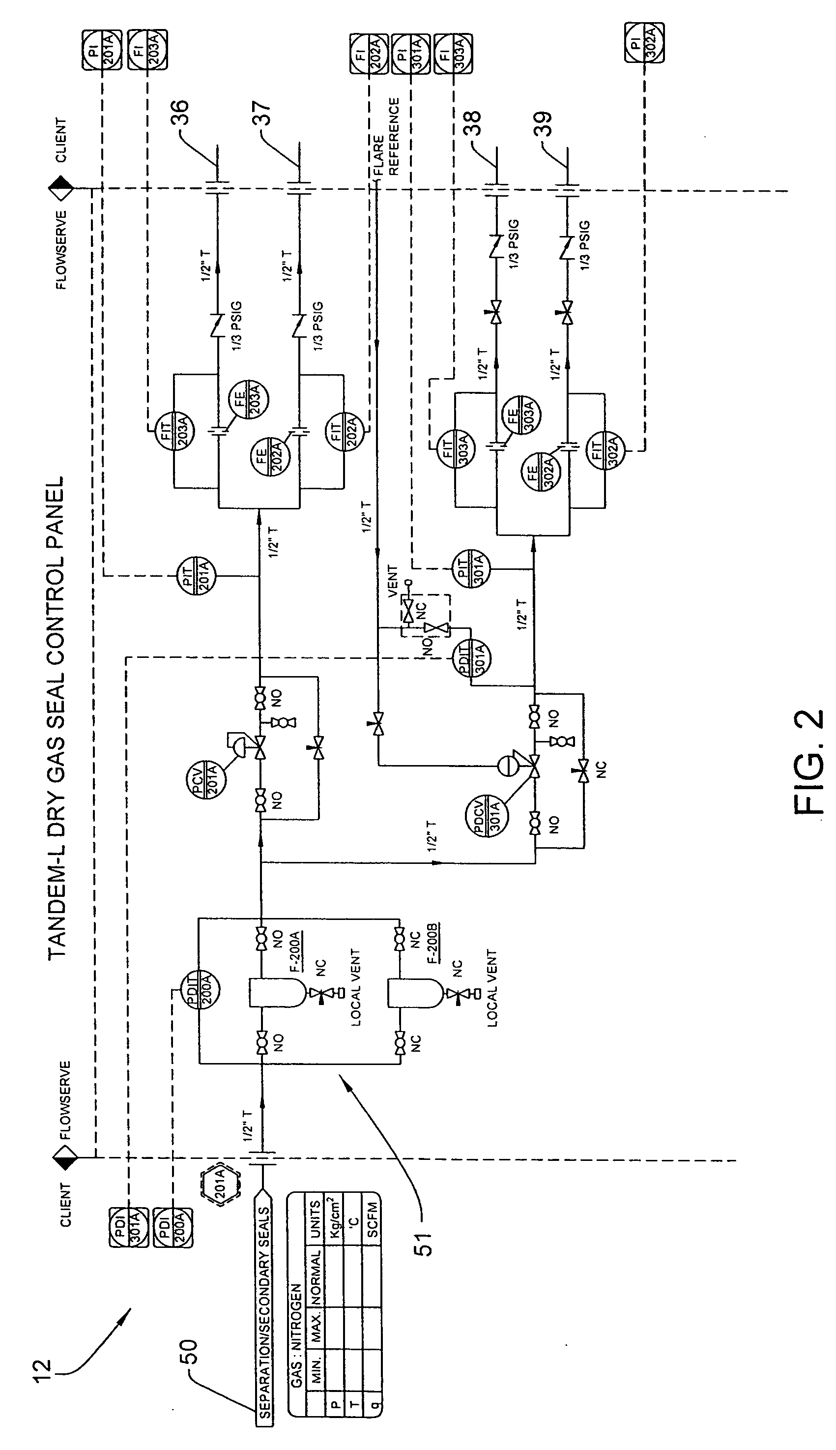
[0015]Referring to FIG. 1, a compressor system 10 is illustrated which is configured for connection to a dry gas seal control panel 12 illustrated in FIGS. 2 and 3, and a dry gas seal leakage recovery system 14 illustrated in FIGS. 4 and 5. While the diagrams of FIGS. 1-5 illustrate in detail the sensors, valves and piping of such systems, the invention relates more generally to the interconnection of these components for recovering dry gas seal leakage and re-injecting same into the compressor system 10. FIG. 6 is included as a legend for the various symbols used in the diagrams of FIGS. 1-5.

[0016]Referring to FIG. 1, the compressor system 10 is illustrated as an exemplary embodiment for use with the recovery system 14, although it will be understood that the recovery system 14 is suitable for use with other compressor and pumping systems and with a variety of mechanical seals and mechanical seal configurations.

[0017]The compressor system 10 comprises a compressor 16 having a proce...


PUM


Abstract

A dry gas seal leakage recovery system is provided which collects seal leakage gas from one or more mechanical seal assemblies, pressurizing and controlling the outlet distribution pressure of the collected seal leakage, and re-injecting the gas back into the compressor or seal supply system.

Description

CROSS-REFERENCE TO RELATED APPLICATIONS[0001]This application is a continuation of International Application No. PCT / US2009 / 006578, with an international filing date of Dec. 15, 2009, which claims the benefit of U.S. Provisional Patent Application No. 61 / 201,777, file Dec. 15, 2008, which is hereby incorporated by reference in its entirety.FIELD OF THE INVENTION[0002]The invention relates to a recovery system for dry gas seals and more particularly, to assist in recovering sealed leakage gas from a mechanical seal assembly used for sealing a rotating shaft of rotating equipment such as compressors.BACKGROUND OF THE INVENTION[0003]Rotating equipment such as compressors include a motor-driven shaft that drives a rotatable component such as an impeller for pumping a fluid such as a gas or other type of processed fluid. Such mechanical seals typically include opposed pairs of relatively rotatable seal rings which are supported in a seal housing and are mounted in surrounding relation to...

Claims


Application Information

Patent Timeline
IPC IPC(8): G05D7/00
CPCF04D29/124F16J15/004F16J15/406F16J15/3492F16J15/3484F04D25/16Y10T137/0318Y10T137/5762
Inventor SEARS, JOHNPATTERSON, SHAWN
Owner FLOWSERVE MANAGEMENT CO
Learn More