Programmable steam trap apparatus

a technology of steam trapping and programmable parts, which is applied in mechanical equipment, transportation and packaging, functional valve types, etc., can solve the problems of high maintenance cost, high maintenance cost, and inefficiency of steam system to waterhammer, and achieve the effect of preventing the loss of steam

Inactive Publication Date: 2010-11-25
TEVA PHARMA IND LTD
View PDF37 Cites 26 Cited by
  • Summary
  • Abstract
  • Description
  • Claims
  • Application Information

AI Technical Summary

Benefits of technology

[0014]The subject application provides an apparatus for removing condensate, air, or non-condensable gas from vapor space in a vapor system while preventing the loss of vapor, the apparatus comprising a first temperature sensor, a second temperature sensor, at a position in the vapor system where condensate, air, or non-condensable gas collect, and which position is different from the position of the first temperature sensor, a pressure sensor, an actuated valve in a position allowing for the release of condensate, air, or non-condensable gas from the vapor space, and a control system which receives output from the first and second temperature sensors and from the pressure sensor and determines whether to open the actuated valve to release condensate, air or non-condensable gas from the vapor space based on temperature reading from the temperature sensors and the pressure reading from the pressure sensor.
[0015]The subject application also provides a method for removing condensate, air, or non-condensable gas from vapor space in a vapor system while preventing the loss of vapor, the method comprising: a) measuring the temperature at a first region in the vapor system; b) measuring the temperature at second region in the vapor system where condensate, air, or non-condensable gas collect, wherein the second region is different from the first region; c) measuring the pressure at a region in the vapor system; d) determining whether the temperatures and pressure obtained in steps a)-c) represents the presence of condensate, air, or non-condensable gas; and e) opening an actuated valve if the temperatures and pressure measured in steps a)-c) is determined to represent presence of condensate, air, or non-condensable gas.
[0016]The

Problems solved by technology

Inadequate steam trapping can lead to various undesirable results from steam sys

Method used


Image

  • Programmable steam trap apparatus
  • Programmable steam trap apparatus
  • Programmable steam trap apparatus

Examples


experiment 1

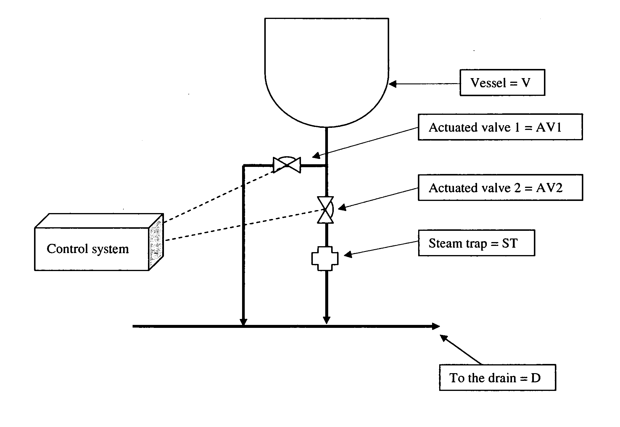
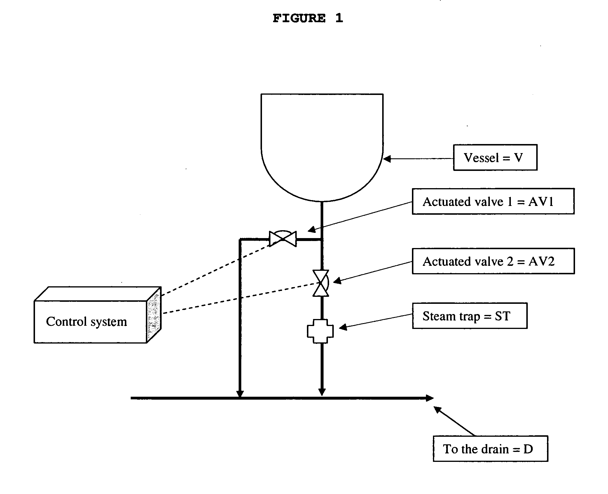
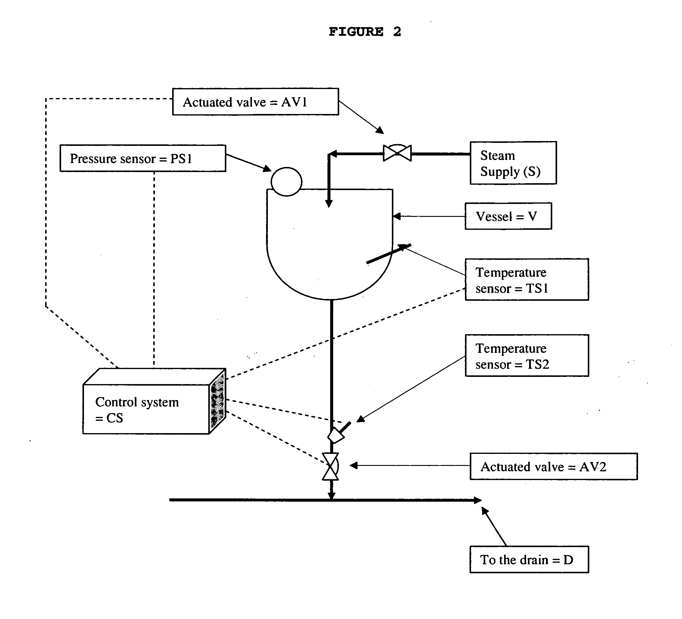
[0111]The steam trap apparatus as shown in FIG. 2 was tested. The apparatus comprises two temperature sensors and a pressure sensor: one temperature sensor (TS2) is located in the actuated valve (AV2) or close to the valve, and the other one (TS1) is located in a vessel (V). The pressure sensor (PS1) is also located in the vessel. Steam is supplied to the vessel via an actuated valve (AV1) and drained through a second actuated valve (AV2).

[0112]An external control system receives the input from the temperature and pressure sensors. A set point for the desired sterilization temperature, for example, 122 or 123° C., is entered (Tsterilization) and the system finds the correlating pressure (Psterilization) from the steam saturation curve. Alternatively, a set point for the sterilization pressure (Psterilization), for example, 1.3 bar gauge, is entered, and the system finds the correlating temperature (Tsterilization). As discussed supra, FDA regulations (1975) require that sterilizatio...


PUM


Abstract

An apparatus and a method for removing condensate and unwanted gas from vapor/liquid systems while preventing steam loss are provided. The steam trap apparatus replaces the automatic valve type steam trap with an efficient, controllable, and programmable steam trap. In addition, the improved steam trap apparatus allows for real-time data collection during sterilization and other operations.

Description

[0001]This application claims the benefit of U.S. Provisional Application No. 61 / 216,602, filed May 19, 2009, the entire content of which is hereby incorporated by reference herein.[0002]Throughout this application various publications and published patents are referenced. The disclosures of these publications in their entireties are hereby incorporated by reference into this application in order to more fully describe the state of the art to which this invention pertains.TECHNICAL FIELD[0003]This application relates to apparatuses, methods, and systems for removing condensate, air, and non-condensable gas from steam space while preventing the loss of steam. In particular, this application relates to an improved steam trap apparatus.BACKGROUND OF THE INVENTION[0004]In industry, steam, the vaporized form of water, is often used as a repository of energy due to water's high heat of vaporization. Energy is introduced and extracted by heat transfer, and transported in the form of steam ...

Claims


Application Information

Patent Timeline
IPC IPC(8): F17D1/16F16K17/38
CPCF16T1/48F16T1/02F16T1/00A61L2/07Y10T137/0396Y10T137/3003Y10T137/7737Y10T137/4266
Inventor ALONI, YEHOSHUAFAHIMIPOOR, OREN
Owner TEVA PHARMA IND LTD
Why Eureka
Try Eureka