Vehicle Charger

a technology for vehicle chargers and charging rods, applied in the direction of electric discharge lamps, transportation and packaging, coupling device connections, etc., can solve the problems of inconvenient use for users, inability to charge electronic products in hand, and inability to apply a proper force to the protruding portion of the vehicle charger, etc., to achieve simple and convenient manufacturing and assembly of the holding frame.

Inactive Publication Date: 2010-11-25
CHENG UEI PRECISION IND CO LTD
View PDF3 Cites 5 Cited by
  • Summary
  • Abstract
  • Description
  • Claims
  • Application Information

AI Technical Summary

Benefits of technology

[0006]As described above, the vehicle charger is provided with the holding frame. When a user want to remove the vehicle charger from a socket of a car or a plane, the base portion is held by the user and pulled rearwards. Thus the vehicle charger can be extracted from the socket conveniently and easily. Furthermore, the structure of the holding frame is simple and convenient to manufacture and assemble.

Problems solved by technology

But, when people travel by a car or a plane, it is impossible to charge the electronic products in hand.
However, as the vehicle charger is miniature, the protruding portion is too small for a user to apply a proper force to the vehicle charger in the process of removing the vehicle charger.
It is inconvenient for the user to use.

Method used


Image

  • Vehicle Charger
  • Vehicle Charger
  • Vehicle Charger

Examples


Embodiment Construction

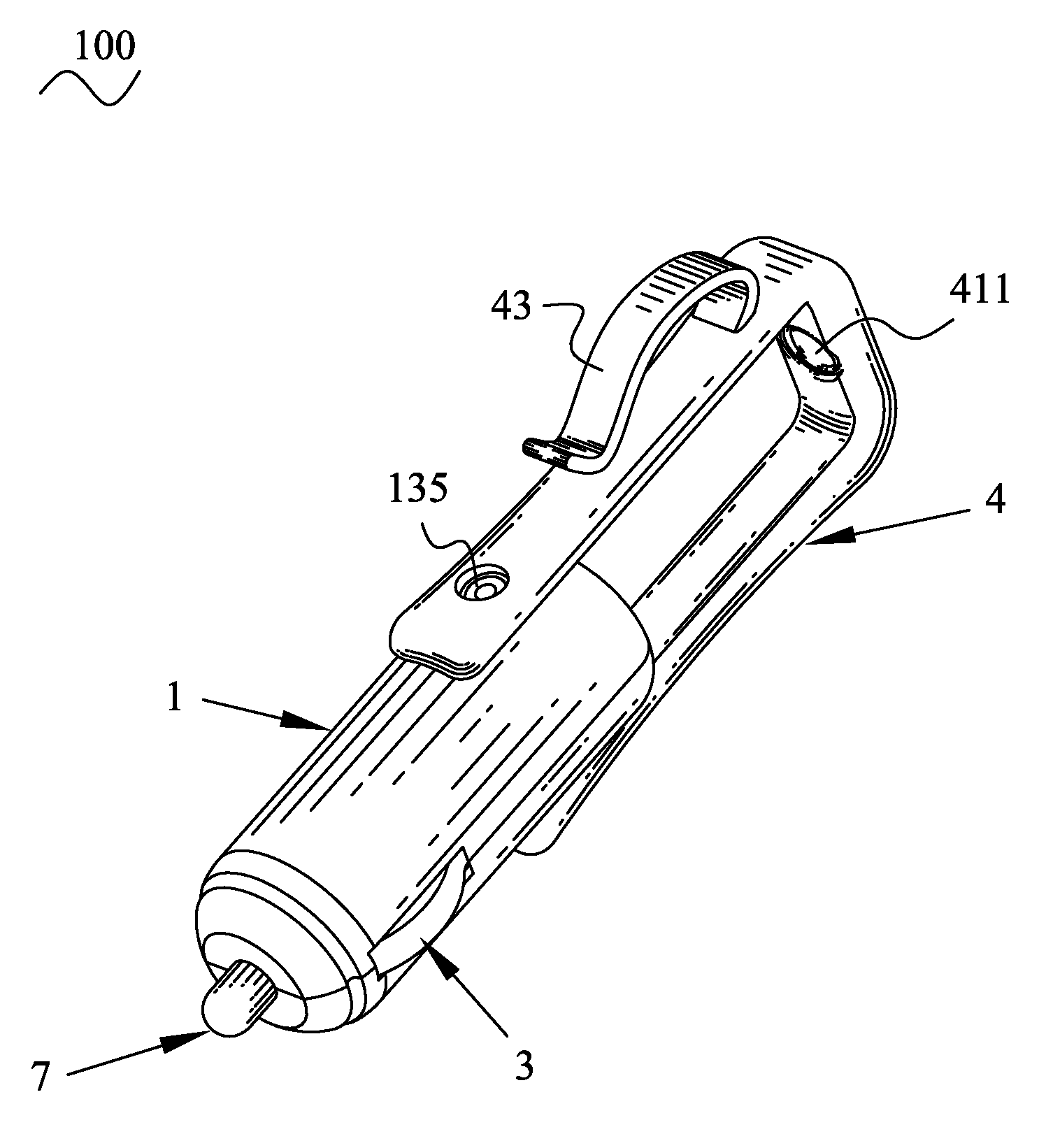
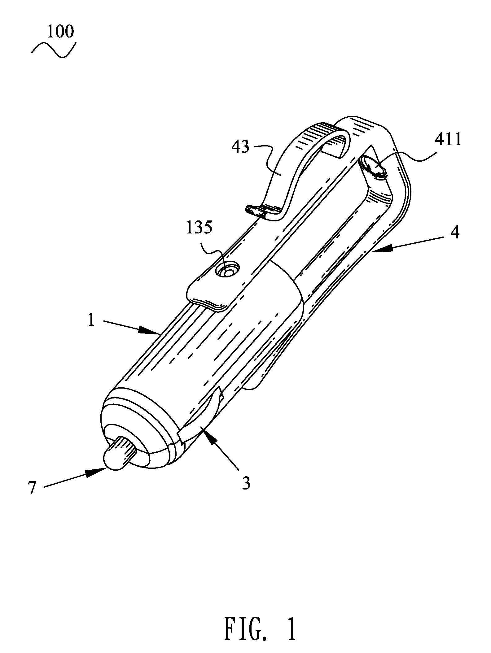
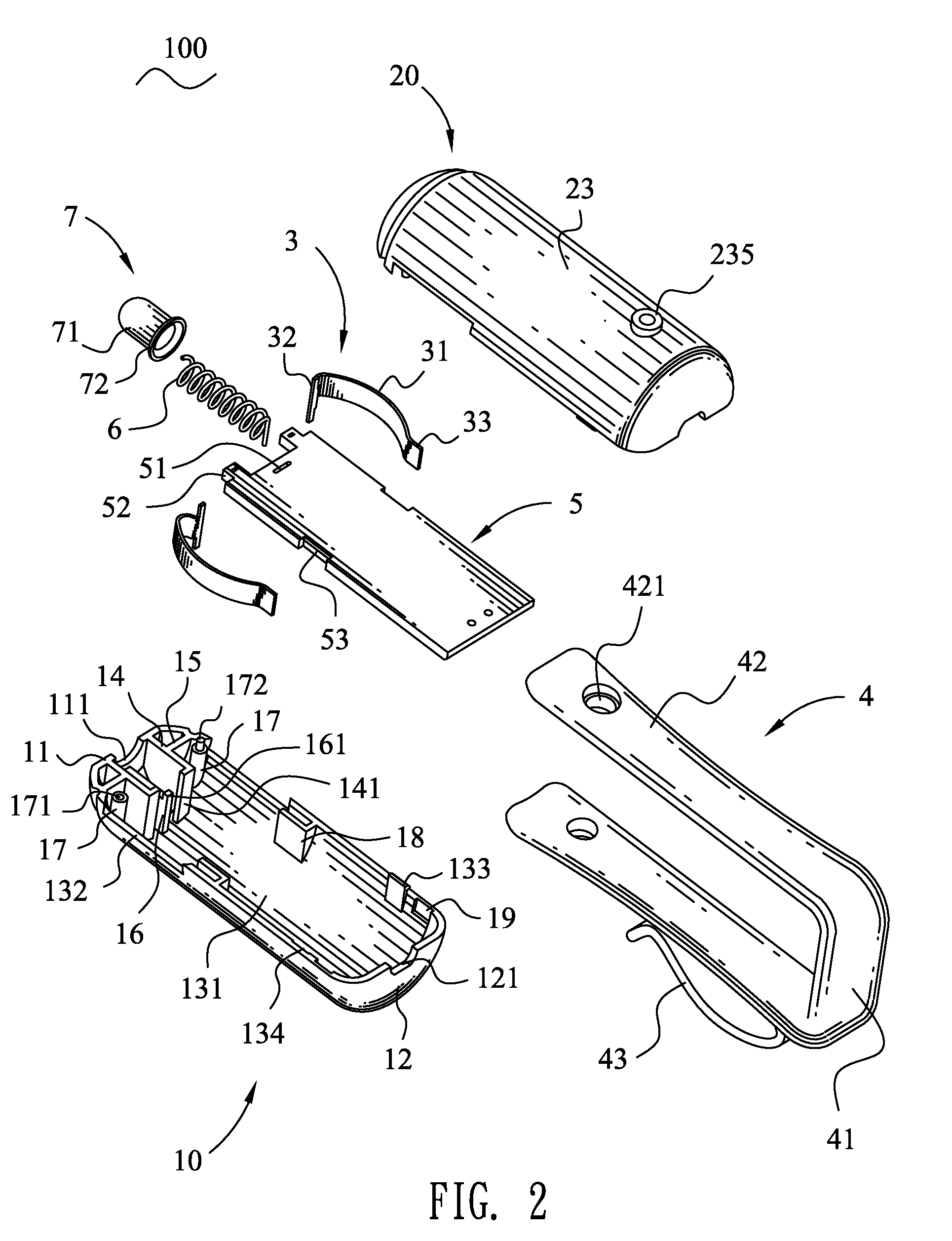
[0013]Referring to FIG. 1 and FIG. 2, a vehicle charger 100 in accordance with the present invention includes a hollow insulating housing 1. The insulating housing 1 defines a front wall, a rear wall facing the front wall, and a lateral wall connecting with the front wall and the rear wall. The front wall has a positive element 7 of substantially pillar shape, partially exposing outside thereof. The lateral wall is symmetrically assembled with two negative elements 3, partially exceeding the lateral wall and adjacent to the front wall, and a holding frame 4 of substantially U shape, adjacent to the rear wall. A printed circuit board (PCB) 5 is received in the insulating housing 1 and electrically connected with the positive element 7 and the negative elements 3.

[0014]With reference to FIGS. 2-3, the insulating housing 1 is divided into two same parts of U shape viewed from its cross-section, named a lower part 10 and an upper part 20. The lower part 10 defines a front wall 11, a rea...


PUM


Abstract

A vehicle charger has a hollow insulating housing which defines an opening at a front wall thereof and a recess at a lateral wall. A printed circuit board is fixedly received in the insulating housing. A positive element is mounted in the insulating housing and electrically connected with the printed circuit board. The positive element has a contact portion which passes through the opening and stretches outside the insulating housing. A negative element assembled in the insulating housing and electrically connected with the printed circuit board has an elastic portion protruding out of the recess partially. A holding frame of U shape has a base portion and two facing connecting arms respectively extending from both ends of the base portion. The connecting arms are pivotally mounted to two substantial opposite portions of the lateral wall biased from the recess.

Description

BACKGROUND OF THE INVENTION[0001]1. Field of the Invention[0002]The present invention relates to a charger, and more particularly to a vehicle charger adapted for charging electronic devices.[0003]2. The Related Art[0004]Nowadays, a variety of electronic products are broadly used, such as mobile phones, MP3, MP4, and the like. The electronic products require to be charged with electric power after being used for a period of time. But, when people travel by a car or a plane, it is impossible to charge the electronic products in hand. Therefore, vehicle chargers inserted into a socket of the car or the plane for charging the electric power to the electronic product are provided on the market. Generally, the conventional vehicle charger has a housing, a positive element and a negative element disposed at a front of the housing for inserting into the socket of the car or the plane, and a wire extending from a rear of the housing for connecting with the electronic products. In order to e...

Claims


Application Information

Patent Timeline
Patent Type & Authority Applications(United States)
IPC IPC(8): H02J7/00H01R24/00
CPCH01R13/6658H01R13/2421
Inventor LIN, CHU-GENG
Owner CHENG UEI PRECISION IND CO LTD
Why Eureka
Try Eureka