
Device and method for detecting touch screen

a technology of touch screen and device, applied in the direction of instruments, electric digital data processing, input/output process of data processing, etc., can solve the problems of difficult to determine the relative motion tendency of two or more touch points, too expensive for most customers,

Inactive Publication Date: 2010-11-25
VIMICRO CORP
View PDF16 Cites 11 Cited by
  • Summary
  • Abstract
  • Description
  • Claims
  • Application Information

AI Technical Summary

Benefits of technology

[0013]There are many features, benefits and advantages in the present invention which will become apparent upon examining the following detailed description of an embodiment thereof, taken in conjunction with the attached drawings.
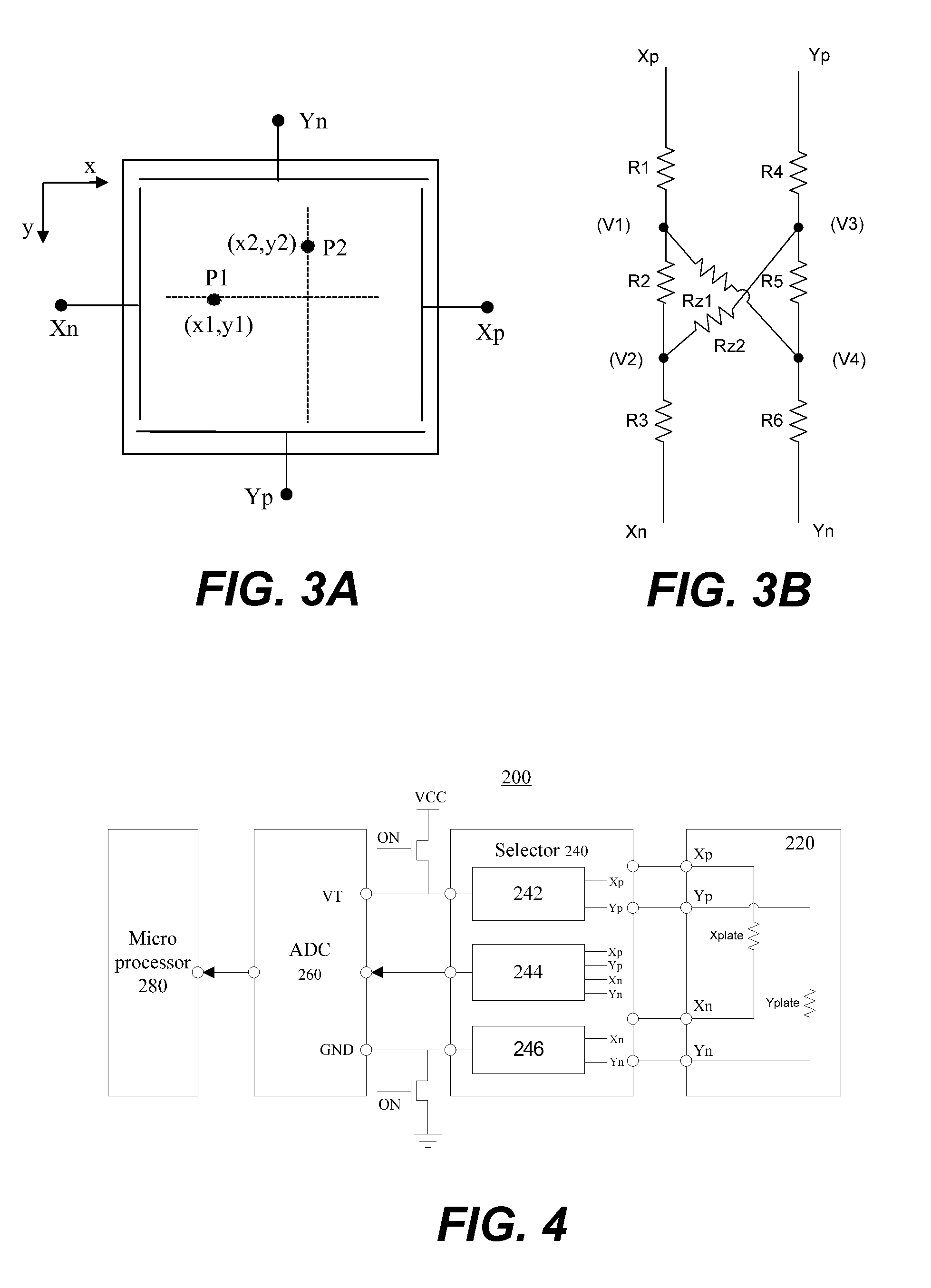
[0021]FIG. 4 is a block diagram showing a touch screen detecting device according to one embodiment of the present invention;
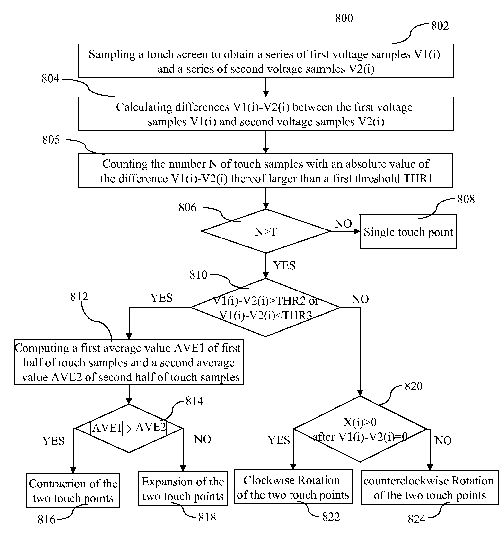
[0012]In general, the present invention is related to techniques for detecting multiple touch points for touch screen. A touch screen includes a first conductive layer and a second conductive layer, each conductive layer having a positive terminal and a negative terminal, an operation of detecting multiple points on a touch screen includes: coupling the positive terminal of the second conductive layer to a positive reference voltage, coupling the negative terminal of the second conductive layer to a negative reference voltage, sampling the positive terminal of the first conductive layer to obtain a series of first voltage samples V1(i), sampling the negative terminal of the first conductive layer to obtain a series of second voltage samples V2(i), wherein i is a sampling number; concluding that a motion tendency of two touch points on the touch screen is contraction when absolute values of the differences V1(i)−V2(i) between the first voltage samples and the second voltage samples tend to increase; and concluding that the motion tendency of two touch points on the touch screen is expansion when the absolute values of the differences V1(i)−V2(i) tend to decrease.

Problems solved by technology

However, techniques for detecting multiple touch points are mostly implemented on an optical touch screen, which are too expensive for most customers.
If there are two or more touch points on the touch screen, it is very difficult to determine a relative motion tendency of the two or more touch points by calculating the coordinates of each touch point.

Method used


Image

  • Device and method for detecting touch screen
  • Device and method for detecting touch screen
  • Device and method for detecting touch screen

Examples


Embodiment Construction

[0038]The detailed description of the present invention is presented largely in terms of procedures, steps, logic blocks, processing, or other symbolic representations that directly or indirectly resemble the operations of devices or systems contemplated in the present invention. These descriptions and representations are typically used by those skilled in the art to most effectively convey the substance of their work to others skilled in the art.

[0039]Reference herein to “one embodiment” or “an embodiment” means that a particular feature, structure, or characteristic described in connection with the embodiment can be included in at least one embodiment of the invention. The appearances of the phrase “in one embodiment” in various places in the specification are not necessarily all referring to the same embodiment, nor are separate or alternative embodiments mutually exclusive of other embodiments. Further, the order of blocks in process flowcharts or diagrams or the use of sequence...


PUM


Abstract

Techniques for detecting multiple touch points for touch screen are disclosed. A touch screen includes a first conductive layer and a second conductive layer, each conductive layer having a positive terminal and a negative terminal, an operation of detecting multiple points on a touch screen includes: coupling the positive terminal of the second conductive layer to a positive reference voltage, coupling the negative terminal of the second conductive layer to a negative reference voltage, sampling the positive terminal of the first conductive layer to obtain a series of first voltage samples V1(i), sampling the negative terminal of the first conductive layer to obtain a series of second voltage samples V2(i), wherein i is a sampling number; concluding that a motion tendency of two touch points on the touch screen is contraction when absolute values of the differences V1(i)−V2(i) between the first voltage samples and the second voltage samples tend to increase; and concluding that the motion tendency of two touch points on the touch screen is expansion when the absolute values of the differences V1(i)−V2(i) tend to decrease.

Description

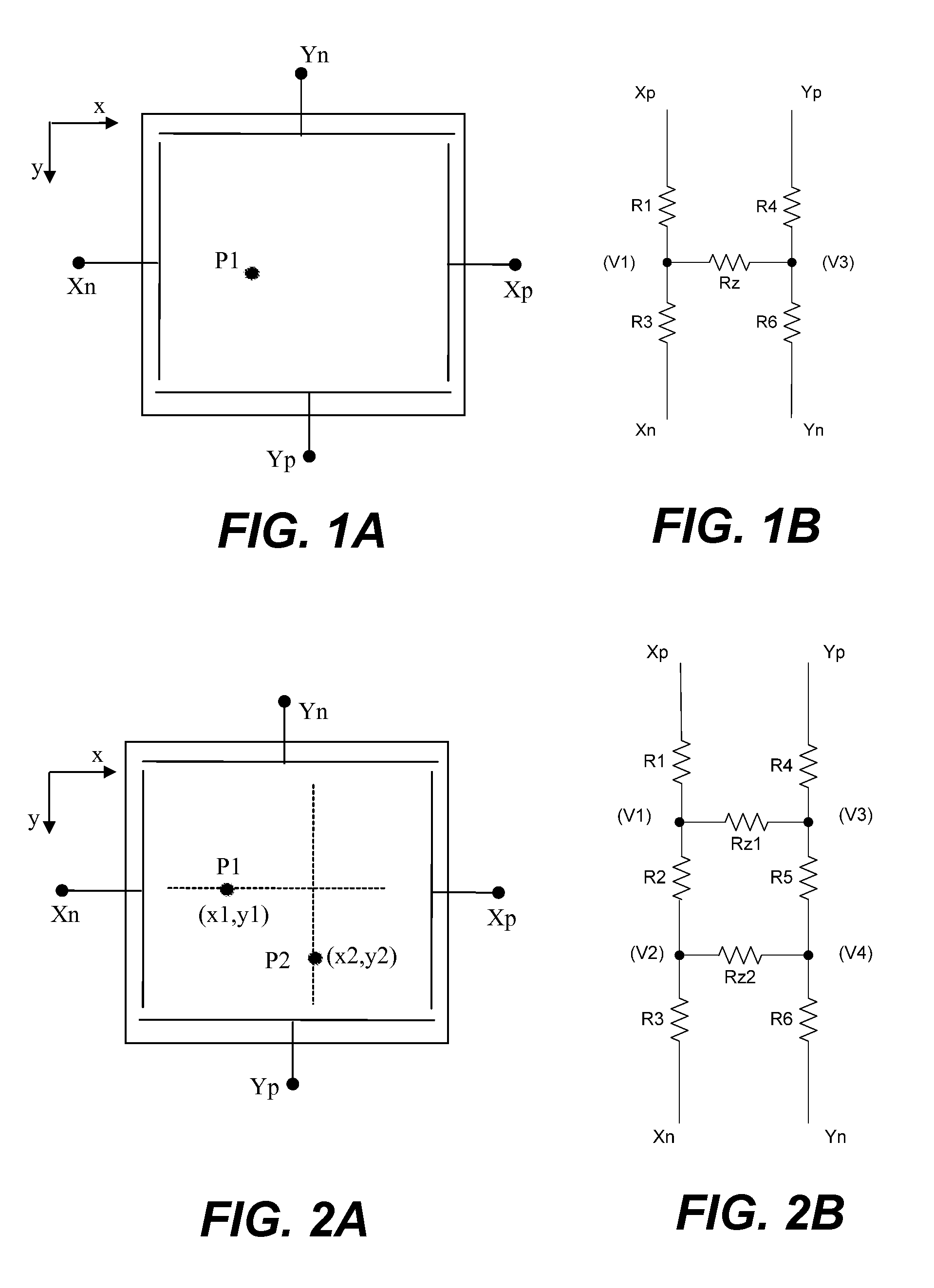
BACKGROUND OF THE INVENTION[0001]1. Field of the Invention[0002]The present invention relates to the techniques for touch screens, and more particularly to techniques for detecting touch screen.[0003]2. Description of Related Art[0004]Touch screens are gradually becoming main means of inputting information to an electronic system. Techniques for detecting multiple touch points are more attractive in the touch screen fields. However, techniques for detecting multiple touch points are mostly implemented on an optical touch screen, which are too expensive for most customers.[0005]FIG. 1A is a schematic diagram showing a conventional four-wire resistive touch screen with a single touch point thereon. The four-wire resistive touch screen includes an X conductive layer and a Y conductive layer. The X conductive layer has a positive terminal Xp and a negative terminal Xn at the ends thereof. The Y conductive layer has a positive terminal Yp and a negative terminal Yn at the ends thereof. T...

Claims


Application Information

Patent Timeline
IPC IPC(8): G06F3/045
CPCG06F3/045
Inventor ZHANG, CHEN
Owner VIMICRO CORP
Learn More