Apparatuses for Printing on Generally Cylindrical Objects and Related Methods

a technology of cylindrical objects and apparatuses, applied in the field of printing, can solve the problems of not being suitable for other markets, not being suitable for hollow cans or two-piece bottles,

Active Publication Date: 2010-11-25
INX INT INK CO
View PDF20 Cites 85 Cited by
  • Summary
  • Abstract
  • Description
  • Claims
  • Application Information

AI Technical Summary

Benefits of technology

[0010]In the one embodiment, each hollow cylindrical object, is hand-loaded and secured by vacuum on a mandrel to prevent slippage, which is part of a carriage assembly that functions to linearly position the can beneath a series of digitally-controlled printheads and rotate the can in front of such printheads while ink is deposited to the can, in order to produce the desired printed design. The ink is also either partially or fully cured immediately after printing by an energy-emitting means positioned directly beneath the can, which is able to function while beneath the printheads or anytime during the functioning of the invention.
[0020]In a third embodiment of the invention, each hollow cylindrical object (or can) is hand-loaded and secured by vacuum on a mandrel to prevent slippage, which is part of a carriage assembly that functions to linearly position the can beneath a series of digitally-controlled printheads and rotate the can in front of such printheads while ink is deposited to the can, in order to produce the desired printed design. The ink is also either partially or fully cured immediately after printing by an energy-emitting means positioned directly beneath the can, which is able to function while beneath the printheads or anytime during the functioning of the invention.

Problems solved by technology

While these methods have great utility in mass production of such objects, they do not lend themselves to other markets, such as novelty advertising on bottles, which benefit from the ability to change designs rapidly.
However, this structure is not suitable for hollow cans or two-piece bottles.

Method used


Image

  • Apparatuses for Printing on Generally Cylindrical Objects and Related Methods
  • Apparatuses for Printing on Generally Cylindrical Objects and Related Methods
  • Apparatuses for Printing on Generally Cylindrical Objects and Related Methods

Examples


Embodiment Construction

[0067]The various embodiments of the present invention and their advantages are best understood by referring to FIGS. 1 through 35 of the drawings. The elements of the drawings are not necessarily to scale, emphasis instead being placed upon clearly illustrating the principles of the invention. Throughout the drawings, like numerals are used for like and corresponding parts of the various drawings.

[0068]This invention may be provided in other specific forms and embodiments without departing from the essential characteristics as described herein. The embodiments described above are to be considered in all aspects as illustrative only and not restrictive in any manner. The following claims rather than the foregoing description indicate the scope of the invention.

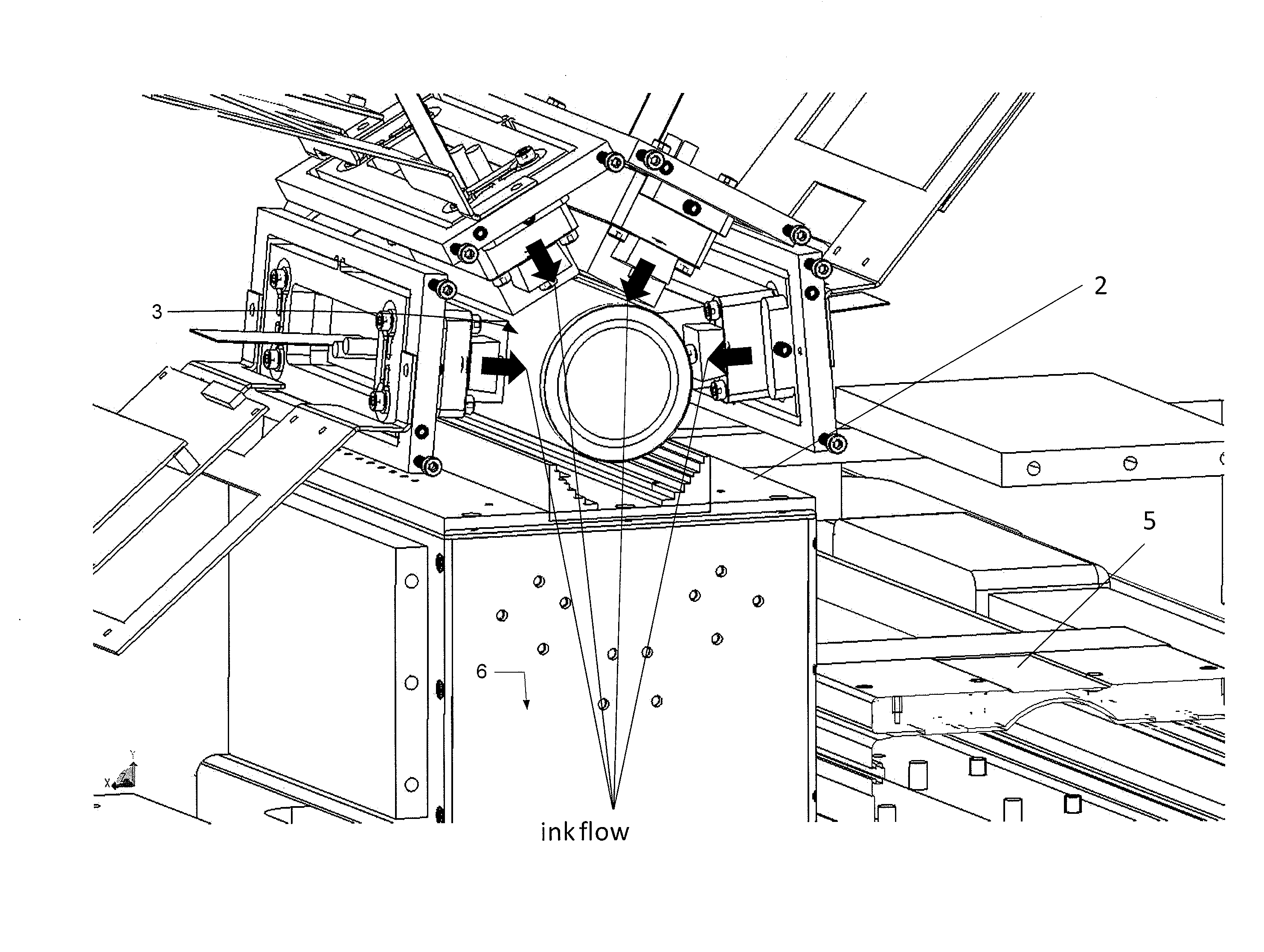
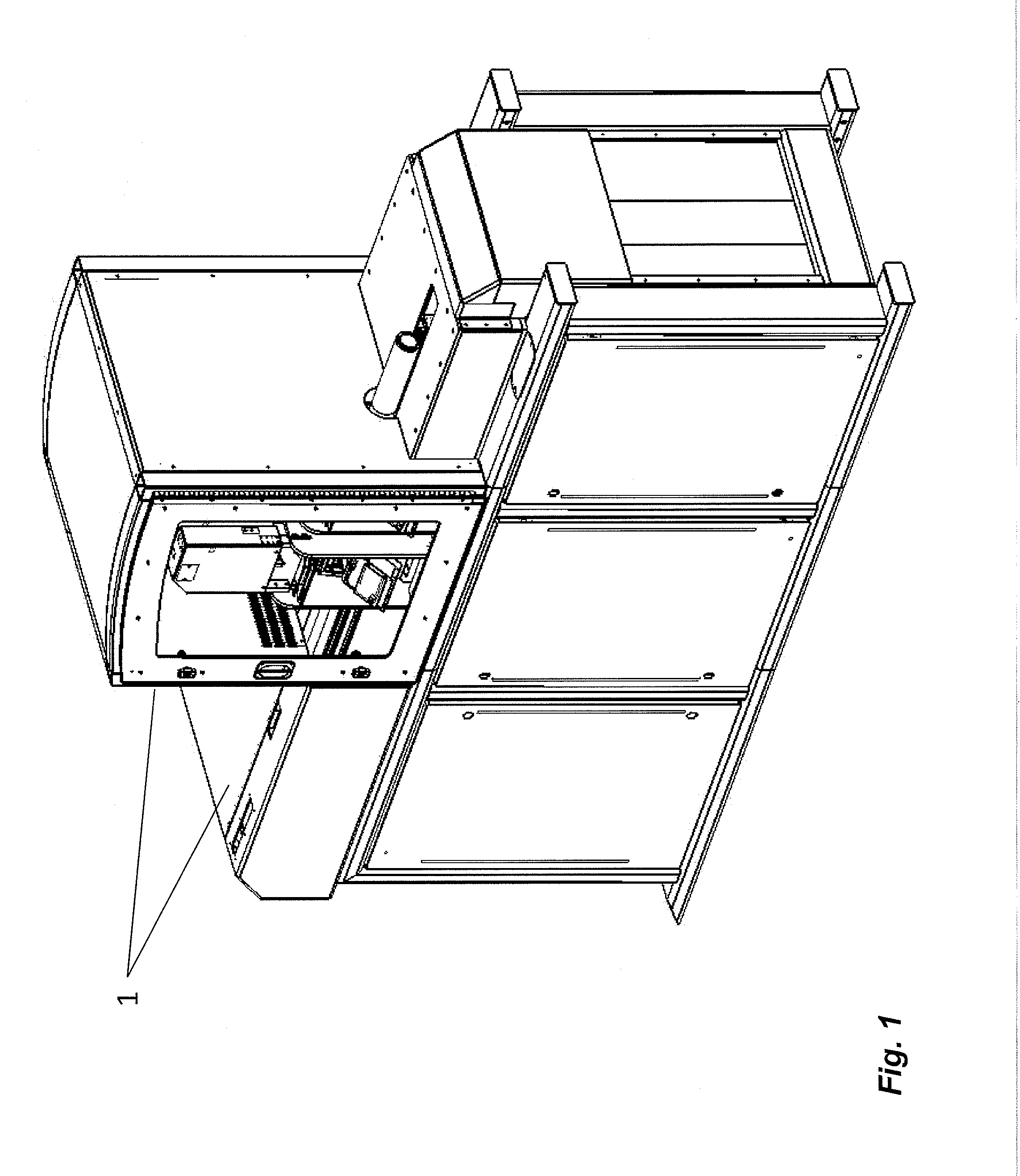
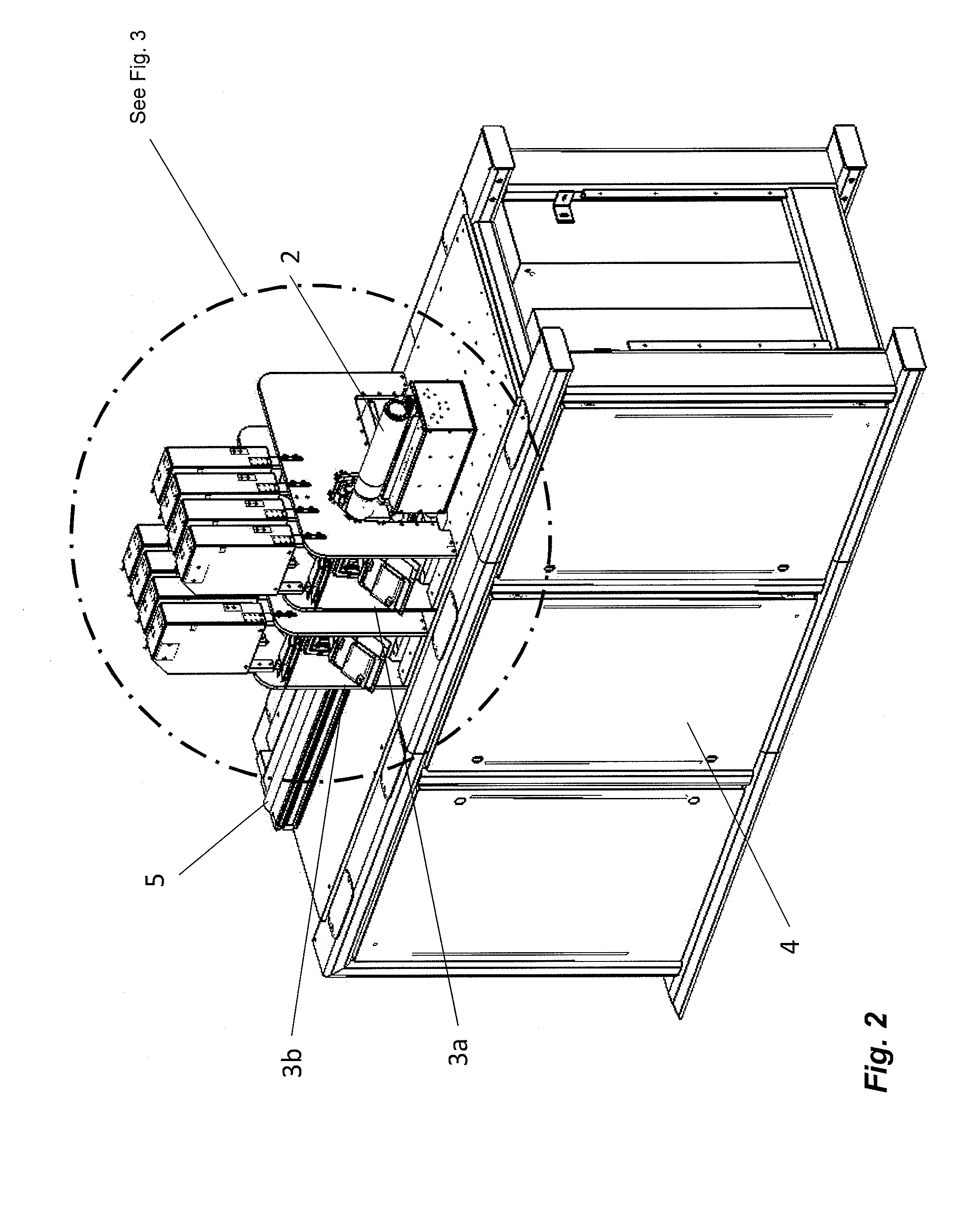
[0069]Referring first to FIG. 1, an exemplary digital printing apparatus for decorating cylindrical objects, for example, cans is illustrated with top covers 1 in place. FIG. 2 depicts the invention with top covers 1 removed f...


PUM


Abstract

An ink jet printer for printing on an at least partially cylindrical objects comprises one or more printheads positioned above a line of travel and a carriage assembly configured to hold an at least partially cylindrical object axially aligned along the line of travel and to position said object relative to the printheads, and then rotate the object relative to said one or more printheads. The printer also includes a curing device located along the line of travel and configured to emit an energy suitable to cure the deposited fluid.

Description

CROSS-REFERENCE TO RELATED APPLICATIONS[0001]This application claims priority to U.S. Provisional Application 61 / 180,251 filed May 21, 2009, and which is incorporated by reference herein.BACKGROUND[0002]1. Field[0003]The present invention relates generally to printing, and particularly, to printing on cylindrical objects, and more particularly to printing on hollow cylindrical objects, such as cans, and hollow, partially cylindrical objects, such as bottles.[0004]2. Description of the Problem and Related Art[0005]Current methods of printing indicia on cylindrical objects, such as cans or bottles, include either spray painting, gravure application, or the like, as is known in the art. While these methods have great utility in mass production of such objects, they do not lend themselves to other markets, such as novelty advertising on bottles, which benefit from the ability to change designs rapidly.[0006]Ink jet printing is well-known, and because it can be digitally controlled using...

Claims


Application Information

Patent Timeline
Patent Type & Authority Applications(United States)
IPC IPC(8): B41J23/00
CPCB41J11/002B41J3/4073B41J11/0021B41J11/00214
Inventor LACAZE, JOHN R.
Owner INX INT INK CO
Why Eureka
Try Eureka