Check patentability & draft patents in minutes with Patsnap Eureka AI!

Active Rotor Alignment Control System And Method

a control system and rotor technology, applied in the direction of machines/engines, mechanical equipment, engine starters, etc., can solve the problems of limiting the amount of minimum designed clearance that can be achieved, unable to account for eccentricities that either develop or are inherent between the rotor and the shroud, and damage to the blades

Inactive Publication Date: 2010-11-25
GENERAL ELECTRIC CO
View PDF12 Cites 13 Cited by
  • Summary
  • Abstract
  • Description
  • Claims
  • Application Information

AI Technical Summary

Benefits of technology

[0008]The present invention provides an active alignment control system and methodology that address certain of the shortcomings of prior control systems. Additional aspects and advantages of the invention will be set forth in part in the following description, or may be obvious from the description, or may be learned through practice of the invention.

Problems solved by technology

On the other hand, if the amount of clearance is too small, then thermal expansion and contraction of the blades, the shroud, and other components may cause the blades to rub the shroud, which can result in damage to the blades, the shroud ring, and the turbine in general.
The conventional passive air-cooling systems, however, assume a uniform circumferential expansion of the rotor and / or shroud and cannot account for eccentricities that either develop or are inherent between the rotor and shroud.
Anticipated eccentricities must be accounted for in design and, thus, these eccentricities limit the amount of minimum designed clearance that can be achieved without rubbing between the blades and shrouds.
This method, however, cannot accurately account for the variations in eccentricities that develop during the operational life of the turbine.

Method used


Image

  • Active Rotor Alignment Control System And Method
  • Active Rotor Alignment Control System And Method
  • Active Rotor Alignment Control System And Method

Examples


Embodiment Construction

[0020]Reference is now made to particular embodiments of the invention, one or more examples of which are illustrated in the drawings. Each embodiment is presented by way of explanation of aspects of the invention, and should not be taken as a limitation of the invention. For example, features illustrated or described with respect to one embodiment may be used with another embodiment to yield still further embodiment. It is intended that the present invention include these and other modifications or variations made to the embodiments described herein.

[0021]Aspects of the present invention will be described herein with respect to a gas turbine configuration. However, it should be appreciated that the present invention is not limited to gas turbines, and is applicable to rotating machines in general wherein it is desired to detect and compensate for eccentricities between a rotor and a surrounding casing structure.

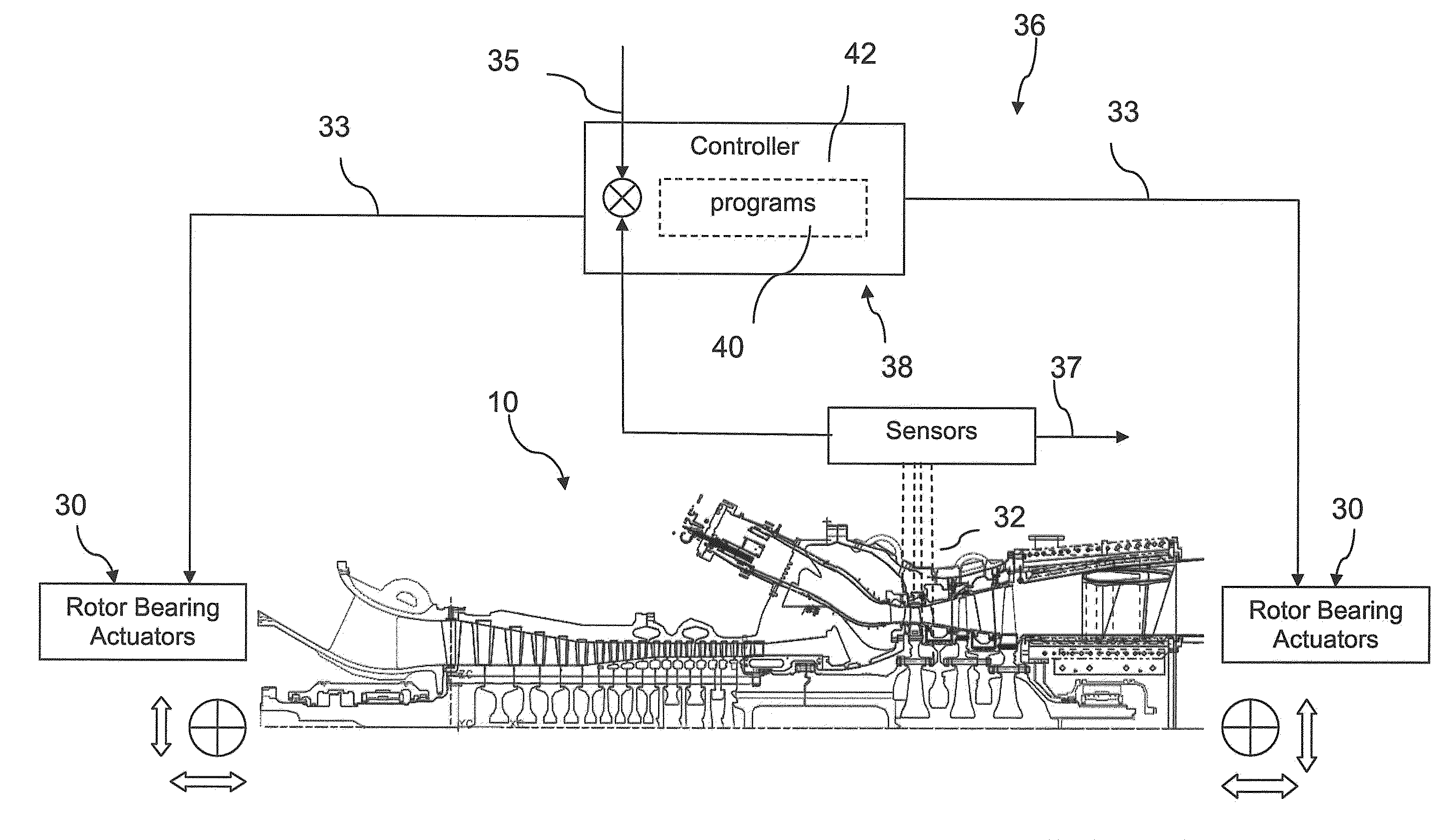
[0022]FIG. 1 illustrates an exemplary embodiment of a conventional rota...


PUM


Abstract

A rotating machine, such as a gas turbine, includes an active rotor alignment clearance control system wherein a plurality of actuators are circumferentially spaced around at least one rotor shaft bearing. The actuators are configured to eccentrically displace the bearing, and thus the rotor shaft, relative to stationary outer casing structure. A plurality of sensors are circumferentially spaced around a component of the casing structure, such as an inner shroud, and measure a parameter indicative of an eccentricity, such as blade tip clearance between the rotor blades and the structure, as the rotor rotates within the structure. A control system in communication with the sensors and actuators is configured to control the actuators to eccentrically displace the rotor by moving the shaft bearing to compensate for eccentricities detected between the rotor and casing structure.

Description

FIELD OF THE INVENTION[0001]The present invention relates generally to rotating machines, such as gas turbines, and more particularly to a system and method for measuring and controlling clearance between the rotor and a surrounding casing structure.BACKGROUND OF THE INVENTION[0002]Rotating machines such as gas turbines have portions commonly referred to as rotors that rotate within stationary casing components, such as a shroud. Clearance dimensions must be maintained between the rotor and the shroud to prevent impacts between the components. This is a particular concern in gas turbines.[0003]A gas turbine uses hot gases emitted from a combustion chamber to rotate a rotor, which typically includes a plurality of rotor blades circumferentially spaced around a shaft. The rotor shaft is coupled to a compressor for supplying compressed air to the combustion chamber and, in some embodiments, to an electric generator for converting the mechanical energy of the rotor to electrical energy....

Claims


Application Information

Patent Timeline
IPC IPC(8): F01D11/22
CPCF01D21/045F01D11/22F01D25/162
Inventor MCCALLUM, MARTEL ALEXANDERBOJAPPA, PARVANGADA GANAPATHYSNIDER, DAVID AUGUST
Owner GENERAL ELECTRIC CO
Features
  • R&D
  • Intellectual Property
  • Life Sciences
  • Materials
  • Tech Scout
  • Unparalleled Data Quality
  • Higher Quality Content
  • 60% Fewer Hallucinations
Learn More