
Hybrid working machine

Inactive Publication Date: 2010-11-25
KOBELCO CONSTR MASCH CO LTD
View PDF51 Cites 9 Cited by
  • Summary
  • Abstract
  • Description
  • Claims
  • Application Information

AI Technical Summary

Benefits of technology

[0024]The present invention is to provide a hybrid working machine capable of efficiently cooling down a power storage device and a controller.

Problems solved by technology

However, in the hybrid working machine, since the hybrid devices are added to limited space of the existing machine, installation space for the devices is restricted.
Therefore, in the known techniques with arrangement on the same plane, a lot of devices including the both devices 17, 18 are concentrated on narrow space, and sufficient space for a passage of the cooling air cannot be obtained around the both devices 17, 18.
In accordance with these points, the known techniques have a problem that the performance and the life of the both devices 17, 18 are lowered.

Method used


Image

  • Hybrid working machine
  • Hybrid working machine
  • Hybrid working machine

Examples


Embodiment Construction

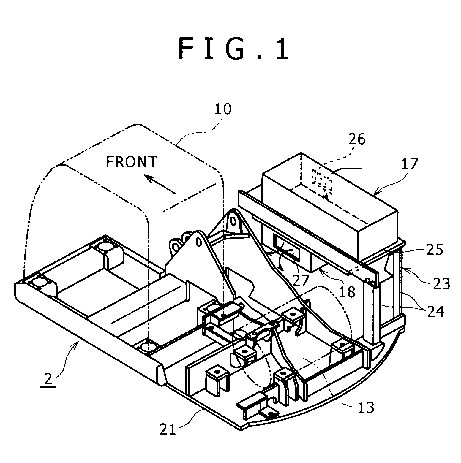
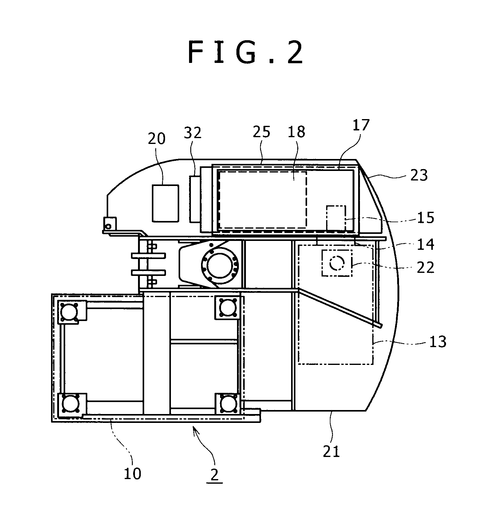
[0045]An embodiment of the present invention will be described with FIGS. 1 to 6.

[0046]In the embodiment, the present invention is applied to a hybrid excavator shown in FIGS. 7 and 8.

[0047]It should be noted that in the embodiment, among the members and devices to be equipped or mounted in the hybrid excavator, the same ones as in FIGS. 7 and 8 are given the same reference numerals.

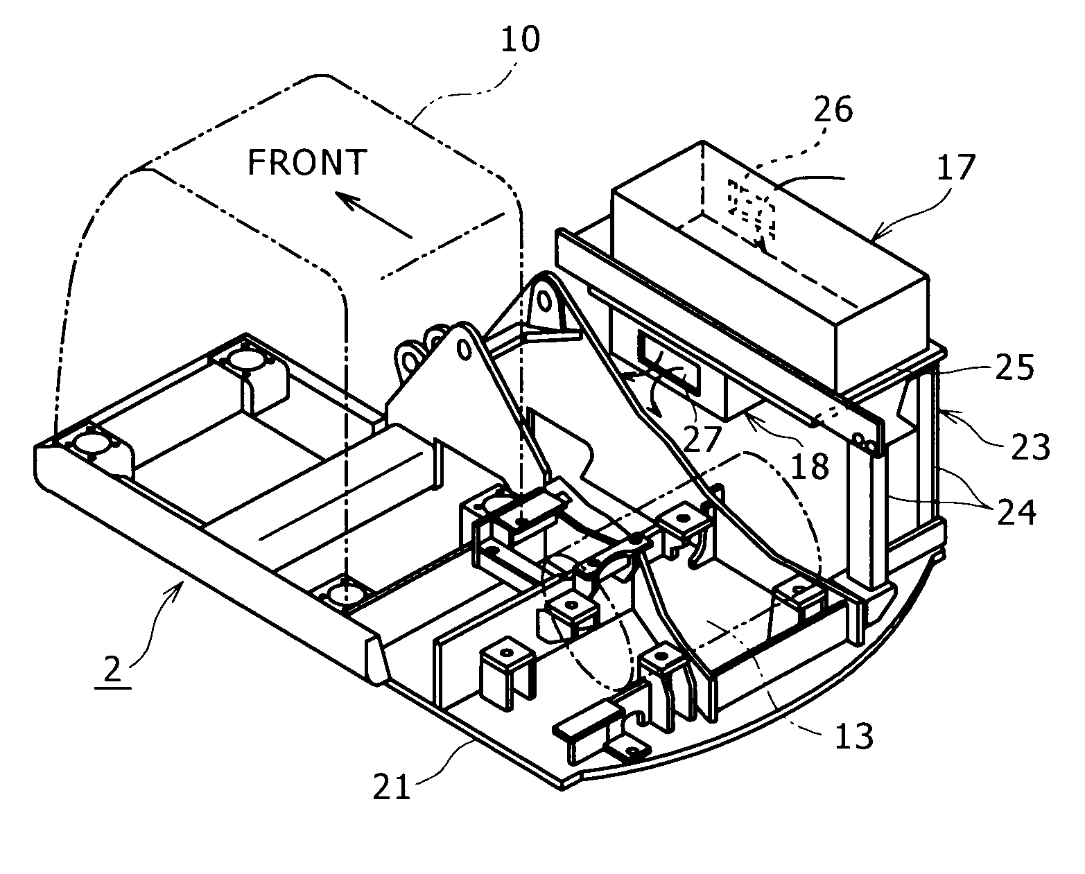
[0048]In FIGS. 1, 2, the reference numeral 21 denotes an upper frame constituting an upper rotating body 2. A working attachment 9 in FIG. 7 is equipped on a substantial center of a front part of this upper frame 21. A cabin 10 is mounted on the left side of the front part of the upper frame 21. An engine 13 is mounted on a rear part of the upper frame 21. A generator motor 14 and a hydraulic pump 15 are connected to the engine 13. In FIG. 2, the reference numeral 22 denotes a muffler of the engine 13.

[0049]A stand 23 is attached to the rear part of the upper frame 21 on a right side deck (on the diagona...


PUM


Abstract

In a hybrid working machine including a power storage device serving as a power source for a generator motor and a controller for controlling this power storage device, the power storage device and the controller being each made up of a main body and casing covering the main body, the power storage device is arranged on the upper side of a top plate of a stand provided on an upper frame, the controller is arranged on the lower side, an intake port is provided in the casing of the power storage device, an exhaust port is provided in the casing of the controller, a ventilation port is provided in the top plate, and the cooling air is fed into the interior of the power storage device and the controller, so that the power storage device and the controller are cooled down.

Description

BACKGROUND OF THE INVENTION[0001]1. Field of the Invention[0002]The present invention relates to a hybrid working machine for which engine power and electric power are used in combination.[0003]2. Description of the Related Art[0004]The related art will be described taking an excavator as an example.[0005]As shown in FIG. 7, in the excavator, an upper rotating body 2 is mounted on a crawler type lower traveling body 1 rotatably around a vertical axis which is vertical to the ground. A working attachment 9 including a boom 3, an arm 4, a bucket 5 and including a boom cylinder 6, an arm cylinder 7 and a bucket cylinder 8 for, respectively, actuating the boom, the arm and the bucket is attached to a front part of this upper rotating body 2.[0006]A cabin 10 is mounted on the left side of the front part of the upper rotating body 2, and a counterweight 11 is equipped on a rear end of the upper rotating body.[0007]An engine room 12 is provided on a rear part of the upper rotating body 2, ...

Claims


Application Information

Patent Timeline
IPC IPC(8): B60H1/24B60K11/04E02F9/00E02F9/20
CPCB60K1/04E02F9/00E02F9/2217E02F9/0858E02F9/2075E02F9/0833B60W2300/17
Inventor SHIMOMURA, KEISUKEYONEZAWA, KOUJIOKUNISHI, TAKAYUKI
Owner KOBELCO CONSTR MASCH CO LTD
Learn More