Power supply apparatus
A power supply device and power supply technology, which is applied in the direction of circuit devices, battery circuit devices, collectors, etc., can solve the problem that the coil is not an optimal method, and achieve the effect of efficiently providing power
- Summary
- Abstract
- Description
- Claims
- Application Information
AI Technical Summary
Problems solved by technology
Method used
Image
Examples
Embodiment 1
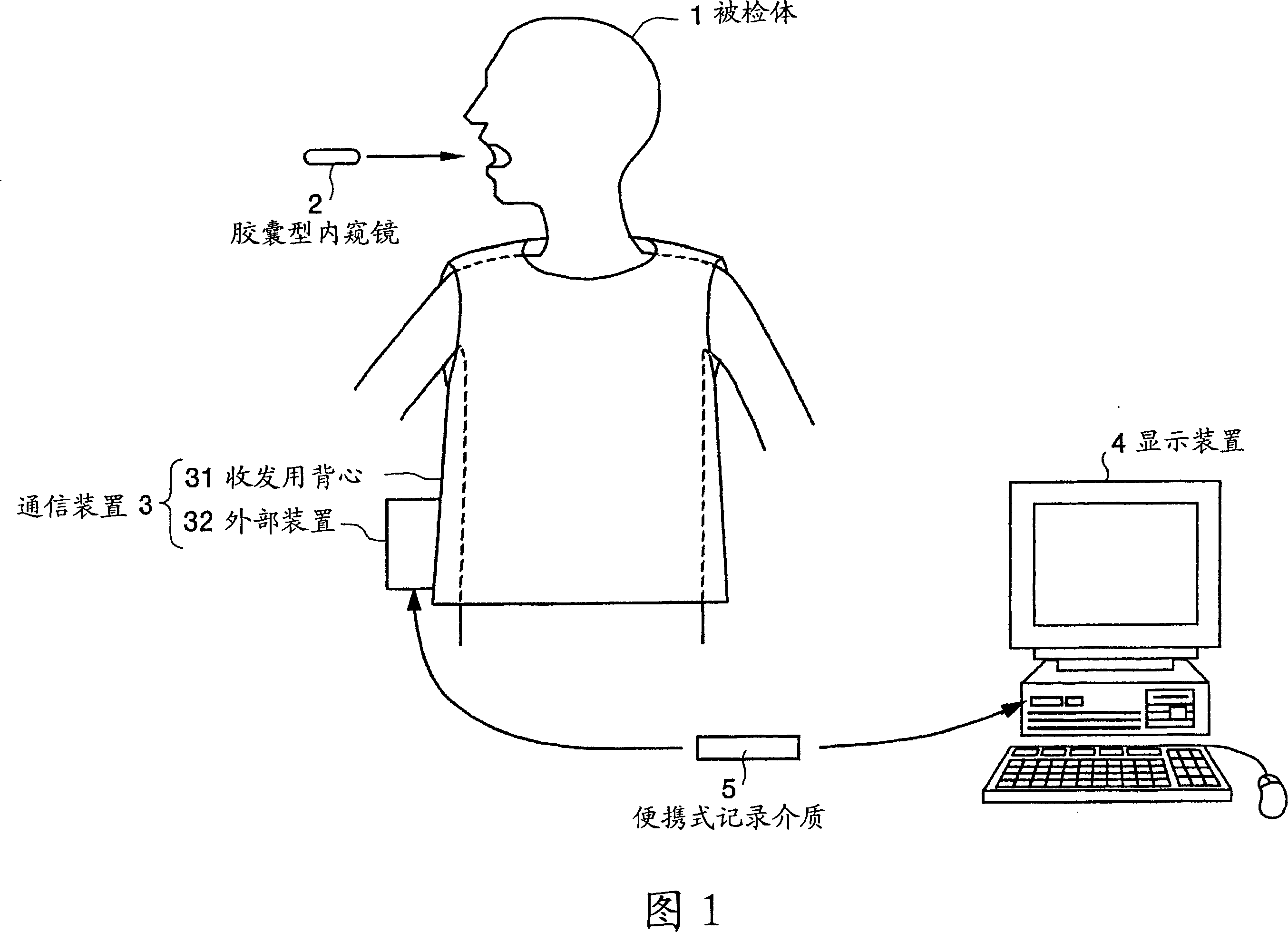
[0030] FIG. 1 is a system conceptual diagram showing the concept of the in-subject information acquisition system according to the present invention. In FIG. 1, the in-subject information acquisition system has: a swallowable capsule endoscope 2 as an in-subject information acquisition device introduced into a body cavity of a subject 1; and a communication device as an extracorporeal device 3. It is arranged outside the subject 1 and performs wireless communication of various information with the capsule endoscope 2. In addition, the in-subject information acquisition system includes: a display device 4 that displays images based on data received by the communication device 3; and a portable recording medium 5 that performs data input and output between the communication device 3 and the display device 4.
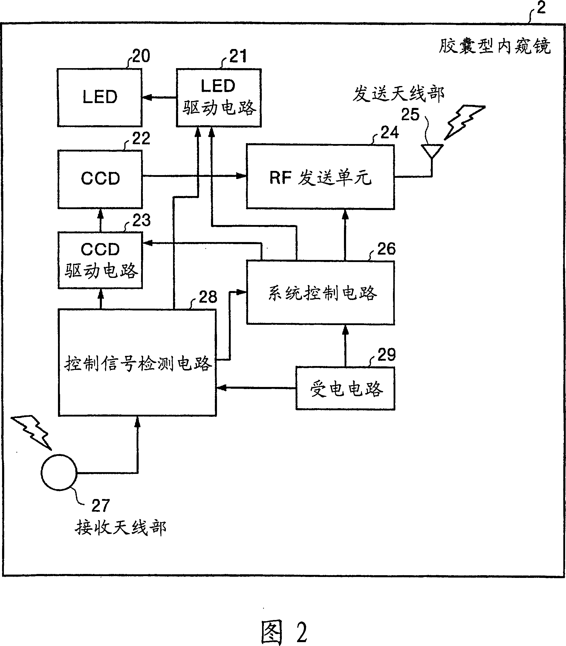
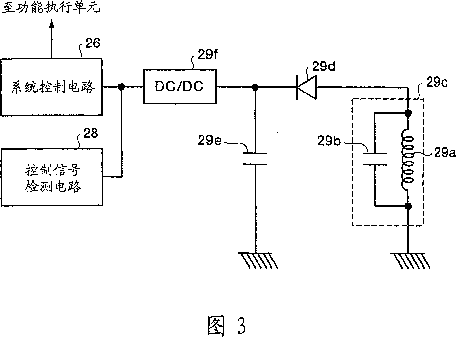
[0031] Fig. 2 is a block diagram showing the internal structure of the capsule endoscope shown in Fig. 1. In addition, in the following drawings, for convenience of descriptio...
Embodiment 2
[0050] Fig. 7 is a plan view showing Example 2 of the vest shown in Fig. 1. In FIG. 7, the difference from the vest according to the first embodiment of FIG. 5 is that it has a coil 70 wound up and down on the inner peripheral surface of the vest 31. The coil 70 is formed of a single conductive wire wound into a spiral loop at a predetermined pitch, and intersects the coils 61 and 62 on the front and rear surfaces of the vest 31.
[0051] Drive circuits 71 and 72 are connected to the coil 70. These drive circuits 71 and 72 are connected to the power supply unit 38 of the external device 32 described above, and the power supply unit 38 supplies power. With this power supply, as with the coils 61 and 62, an AC magnetic field of a predetermined strength is generated in the coil 70.
[0052] Fig. 8 is a diagram showing AC magnetic fields generated by the respective coils 61, 62, and 70 shown in Fig. 7. In FIG. 8, the magnetic fluxes 61a and 62a of the coils 61 and 62 are the same as i...
Embodiment 3
[0056] Fig. 9 is a plan view showing Example 3 of the vest shown in Fig. 1. In FIG. 9, the coil 67 is formed by a single conductive wire. The formed coil 67 is arranged to cross each other on the front surface and the rear surface of the inner peripheral surface of the vest 31, and is continuous at a predetermined pitch in the vertical direction on the side surfaces. Ground winding.
[0057]Drive circuits 68 and 69 are connected to the coil 67, and these drive circuits 68 and 69 are connected to the power supply unit 38 of the external device 32 described above, and the power supply unit 38 supplies power. With this power supply, as in the first and second embodiments, the coil 67 generates an alternating magnetic field of predetermined strength.
[0058] That is, the central axis corresponding to each turn is continuously formed in the coil 67, and the magnetic flux of the coil 67 is formed to be radial around these central axes, cross each other and extend in multiple directions...
PUM
 Abstract
Description
Claims
Application Information
 - R&D
- Intellectual Property
- Life Sciences
- Materials
- Tech Scout
- Unparalleled Data Quality
- Higher Quality Content
- 60% Fewer Hallucinations
Browse by: Latest US Patents, China's latest patents, Technical Efficacy Thesaurus, Application Domain, Technology Topic, Popular Technical Reports.
© 2025 PatSnap. All rights reserved.Legal|Privacy policy|Modern Slavery Act Transparency Statement|Sitemap|About US| Contact US: help@patsnap.com


