
Circuit board including directional coupler with power amplifier module

Inactive Publication Date: 2020-02-20
MICROELECTRONICS TECH INC
View PDF0 Cites 0 Cited by
  • Summary
  • Abstract
  • Description
  • Claims
  • Application Information

AI Technical Summary

Benefits of technology

The present patent text describes a power amplifier module that is more efficient in amplifying signals. This is achieved by eliminating a transmission line that may cause power loss, which results in a more effective use of power.

Problems solved by technology

A length of the 50-ohm transmission line results in power loss.
As a result, the comparative power amplifier module is relatively power inefficient.

Method used


Image

  • Circuit board including directional coupler with power amplifier module
  • Circuit board including directional coupler with power amplifier module
  • Circuit board including directional coupler with power amplifier module

Examples


Embodiment Construction

[0036]Embodiments, or examples, of the disclosure illustrated in the drawings are now described using specific language. It shall be understood that no limitation of the scope of the disclosure is hereby intended. Any alteration or modification of the described embodiments, and any further applications of principles described in this document, are to be considered as normally occurring to one of ordinary skill in the art to which the disclosure relates. Reference numerals may be repeated throughout the embodiments, but this does not necessarily mean that feature(s) of one embodiment apply to another embodiment, even if they share the same reference numeral.

[0037]It shall be understood that, although the terms first, second, third, etc. may be used herein to describe various elements, components, regions, layers or sections, these elements, components, regions, layers or sections are not limited by these terms. Rather, these terms are merely used to distinguish one element, component...


PUM


Abstract

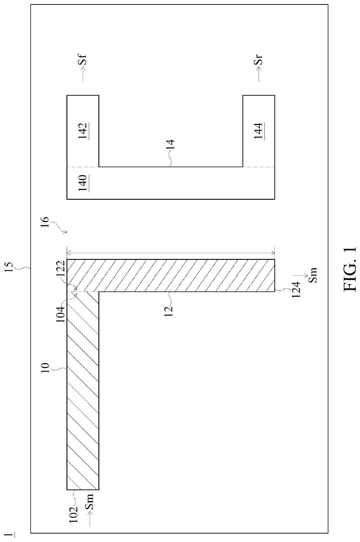
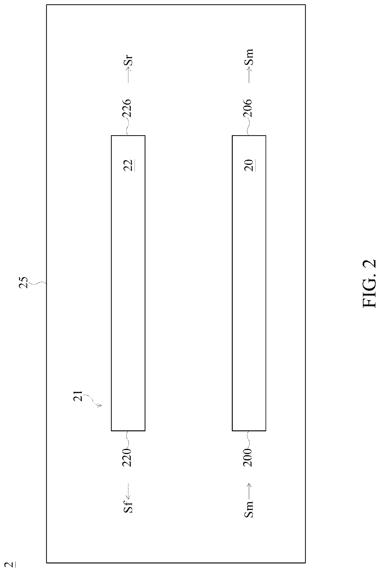
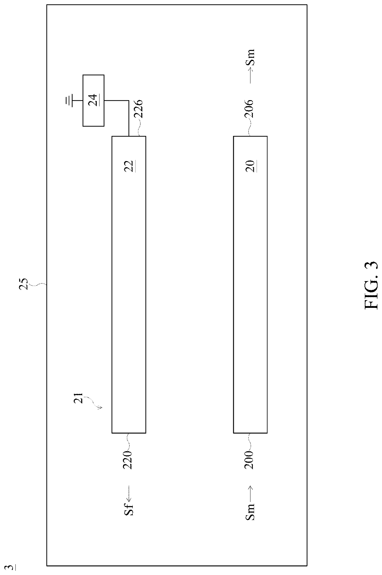
The present disclosure provides an output matching pattern of a power amplifier module. The output matching pattern of the power amplifier module includes a first transmission line and a second transmission line. The first transmission line, in a circuit board, is configured for impedance conversion, and is configured to transfer a signal. The second transmission line, in the circuit board, is configured to sample the signal from the first transmission line. The first transmission line and the second transmission line are separate from each other, and extend and trend in the same direction.

Description

TECHNICAL FIELD[0001]The present disclosure relates to a circuit board and a power amplifier module using the same, and more particularly, to a circuit board including a directional coupler.DISCUSSION OF THE BACKGROUND[0002]Directional couplers are most frequently constructed from two coupled transmission lines set close enough together such that energy passing through one is coupled to the other. This technique is favored at microwave frequencies for which transmission line designs are commonly used to implement many circuit elements. The most common form of directional coupler is a pair of coupled transmission lines. Such arrangement can be realized in a number of technologies including coaxial and planar technologies (stripline and microstripline).[0003]This Discussion of the Background section is for background information only. The statements in this Discussion of the Background are not an admission that the subject matter disclosed in this section constitutes a prior art to th...

Claims


Application Information

Patent Timeline
IPC IPC(8): H01P5/18H03F3/21H01P3/08
CPCH03F3/211H01P5/18H01P3/081H01P5/185H03F1/56H03F3/60
Inventor LIOU, MING-CHECHANG, SHIN-CHANG
Owner MICROELECTRONICS TECH INC
Learn More