
Wellhead Assembly

a technology of wellhead and assembly, which is applied in the direction of sealing/packing, drilling pipes, and wellbore/well accessories, etc., can solve the problems of limited access for downhole tools to enter the well, obviating the need to remove, and reducing the number of horizontal trees

Active Publication Date: 2010-12-02
ONESUBSEA IP UK LTD
View PDF33 Cites 47 Cited by
  • Summary
  • Abstract
  • Description
  • Claims
  • Application Information

AI Technical Summary

Benefits of technology

[0019]In use, the tree body of the assembly and the connector are separate components, which when combined, form a horizontal tree that may be used in the same manner as the known horizontal trees described hereinbefore. However, a number of significant advantages arise from the use of a tree body and separate connector, such as a tree re-entry connection.
[0050]As noted above, the embodiments are particularly suitable and offer significant advantages in the manufacture, shipping, and installation of wellhead installations in remote locations, in particular subsea wellheads where the installation is a considerable distance from the rig or platform operating the well. The assemblies of the present invention are particularly advantageous when used in deep water locations, that is wellhead installations at a depth of up to 3,000 m (10,0000 feet).

Problems solved by technology

However, the access for downhole tools to enter the well is limited by the diameter of the vertical bore or bores in the Christmas tree.
This obviates the need to remove the tree when downhole operations are required, a dangerous task, in particular when dealing with subsea wellhead installations which may be a considerable distance below the surface of sea and, hence, from the rig or platform servicing them.
However, a number of problems remain with horizontal trees.
As a result, the body of a horizontal tree is a massive component, the size of which limits the ability to machine and form other features or components.
The massive size of the tree body also limits the extent to which other features may be incorporated into the tree body, such as certain flowloops or cross-over lines.
The inability to include the aforementioned features into the horizontal tree body may detract from the integrity of the tree.
As noted above, it has been the case that the valves necessary to control the production fluid flow cannot necessarily be accommodated within the tree body.
This results in a potential fluid leak path at every joint of the bolt-on assemblies.
The potential for a fluid leak is particularly high at the very high fluid pressures encountered in the production flow path, in which fluid is flowing at full well pressure before reaching the production choke.

Method used


Image

  • Wellhead Assembly
  • Wellhead Assembly
  • Wellhead Assembly

Examples


Embodiment Construction

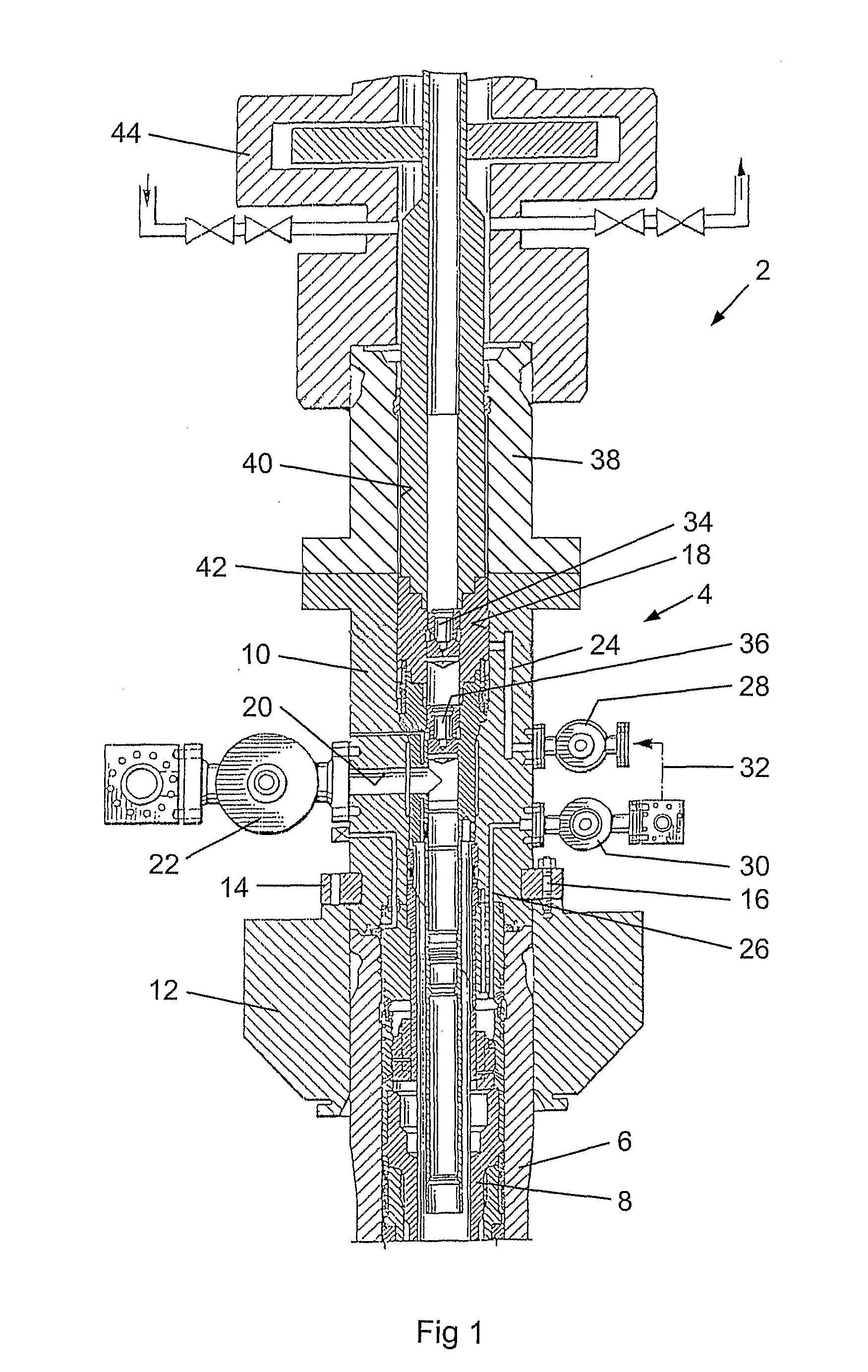
[0058]Referring to FIG. 1, there is shown a wellhead assembly, generally indicated as 2, comprising a horizontal tree assembly, generally indicated as 4, according to a first embodiment. Shown in FIG. 1 is the upper end of a cased well having a wellhead housing 6, in which an uppermost production casing hanger 8 is mounted in conventional manner.

[0059]The horizontal tree assembly 4 comprises a tree body 10, mounted to the upper end of the wellhead housing 6 by means of a production connector 12, a connection ring 14 and bolts 16.

[0060]The tree body 10 has an internal bore 18, extending along the central longitudinal axis of the tree body and aligned with the internal bore in the wellhead housing 6. A lateral bore 20 extends from the internal bore 18 through the tree body 10. In operation, the lateral bore 20 provides a flowpath for production fluid from the wellhead casing 6 via the internal bore 18 of the tree body 10. A production master valve 22 is mounted to the exterior of the ...


PUM


Abstract

An assembly for use on a wellhead includes a tree body including an internal main bore arranged in use to be aligned with the bore of a wellhead housing; the tree body including a lateral bore extending through the tree body from the internal bore; the tree body further including means for connecting to a connector so as to align the internal bore of the tree body with an internal bore in the connector, in use the tree body and the connector together forming a horizontal tree. The tree body may include one or more integrally formed bores and valves to provide fluid flowpaths for the annulus and / or cross-over functions. A wellhead assembly including the tree assembly is also provided.

Description

CROSS-REFERENCE TO RELATED APPLICATIONS[0001]This application is a national phase entry of prior PCT Application No. PCT / GB2007 / 003149, filed 17 Aug. 2007, and entitled Wellhead Assembly, hereby incorporated herein by reference, which claims the benefit of UK Patent Application No. 0616423.0, filed 18 Aug. 2006, and entitled Wellhead Assembly, hereby incorporated herein by reference.STATEMENT REGARDING FEDERALLY SPONSORED RESEARCH OR DEVELOPMENT[0002]Not Applicable.BACKGROUND[0003]The present invention relates to a wellhead assembly, for example a wellhead completion assembly, and to a horizontal tree (also referred to as a Spool Tree™) for use in such an assembly. The invention is particularly concerned with assemblies for use in subsea wellhead installations.[0004]It is well known in the art of oil and gas exploration and production for wells to be cased and suspended from a wellhead housing. Once the well has been completed and production is to begin, it is conventional practice ...

Claims


Application Information

Patent Timeline
Patent Type & Authority Applications(United States)
IPC IPC(8): E21B33/035
CPCE21B33/038E21B33/0353E21B33/035E21B33/043
Inventor GARBETT, KEITHBEAN, ANDREWHOPPER, HANS PAUL
Owner ONESUBSEA IP UK LTD
Learn More