
Eureka
For R&D, Eureka makes reading and utilizing patents & technical documents easy.
Eureka AIR
Designed for self-driven R&D workflows. Generate viable solutions, solve complex R&D challenges, empower your innovation with AI.

Eureka Materials
Designed for material experts only. Revolutionize your material R&D, from search, analyze, to developing new materials.

TechResearch
Generate reliable direction feasibility study reports for your R&D in just a few steps.

TechSeek
Discover and master advanced knowledge NOW. Basics, ideas, possibilities, all at once.

TechMind
As an expert in R&D Theories, TechMind can generates customized viable solutions instantly.

TechRisk
Analyze your overall solution with one click, know your potential R&D risks in advance.

TechMonitor
Get weekly tech updates, stay abreast of the latest tech innovations and key insights.
Wellbore Shut Off Valve with Hydraulic Actuator System
- Summary
- Abstract
- Description
- Claims
- Application Information
AI Technical Summary
Problems solved by technology
Method used
Image

Examples
Embodiment Construction
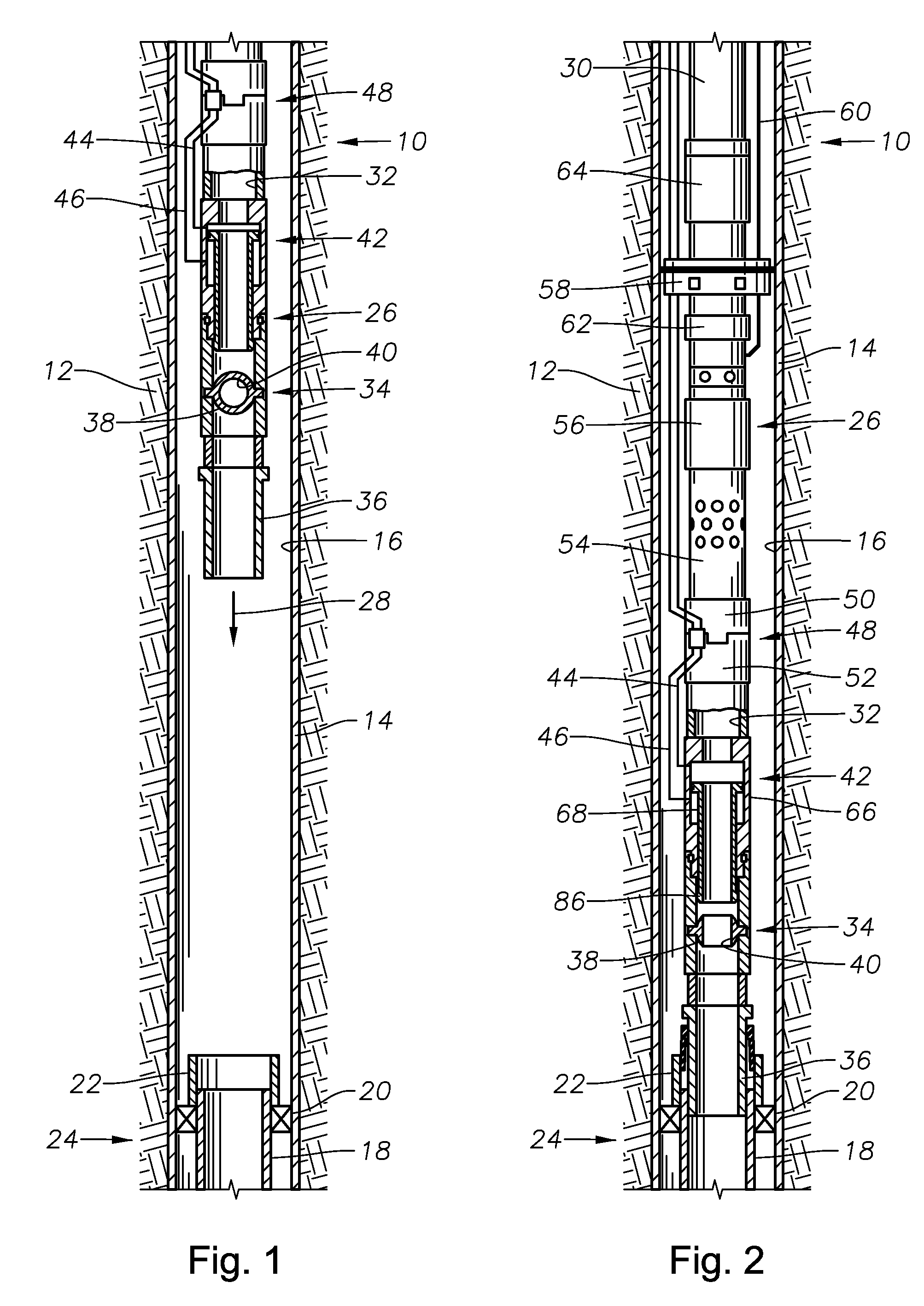
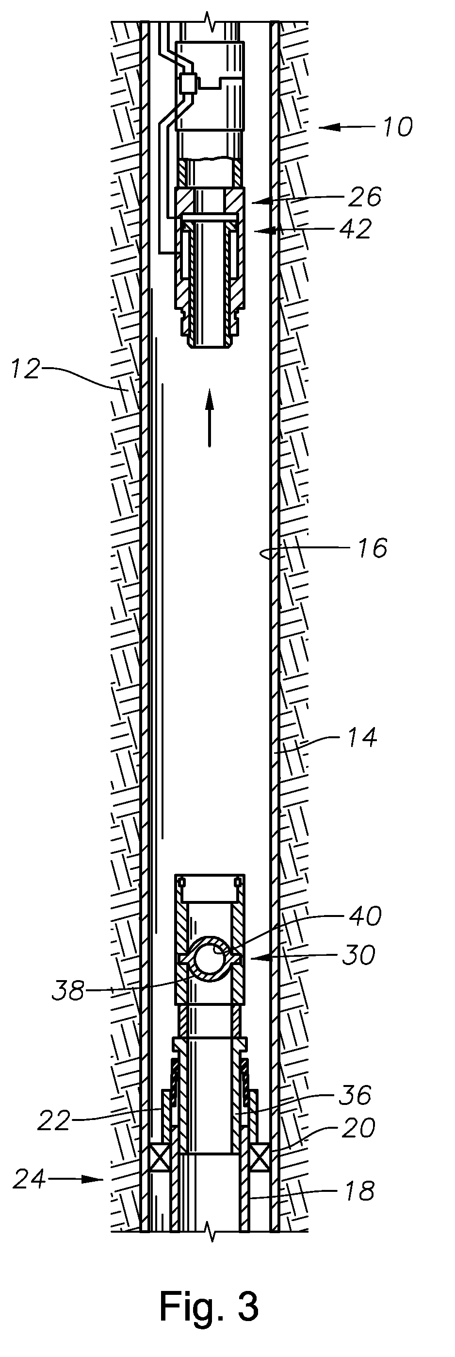
[0019]Referring first to FIGS. 1 and 2, there is depicted an exemplary wellbore 10 which has been drilled into the earth 12 and is lined with casing 14 which will extend upwardly toward the surface of the wellbore 10. The casing 14 defines a central flowbore 16. The wellbore 10 contains an exemplary production string assembly which will be used to illustrate the invention. It is noted that, in this example, the section of the wellbore 10 which is depicted is representative of an upper pump-assisted completion within the wellbore 10 and that one or more additional completions may be located below the wellbore portion that is shown. As a result, a lower portion of production tubing string 18 is shown extending downwardly within the flowbore 16 from lower packer 20. A landing anchor 22 extends axially upwardly from the packer 20. Collectively, the lower production tubing string portion 18 and elements suspended below it, as well as the packer 20 and anchor 22 may be thought of as a low...
PUM
 Abstract
Description
Claims
Application Information
 - R&D Engineer
- R&D Manager
- IP Professional
- Industry Leading Data Capabilities
- Powerful AI technology
- Patent DNA Extraction
Browse by: Latest US Patents, China's latest patents, Technical Efficacy Thesaurus, Application Domain, Technology Topic, Popular Technical Reports.
© 2024 PatSnap. All rights reserved.Legal|Privacy policy|Modern Slavery Act Transparency Statement|Sitemap|About US| Contact US: help@patsnap.com